Yaskawa: VFD Panels and Short Circuit Current
Why You Should Care about Short Circuit Current Rating
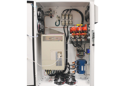
If you ignore the short circuit current rating (SCCR) of an industrial panel it might just go away anyway. By go away I mean that the panel might just self-destruct.
If the available current or energy that reaches the panel in the event of a short circuit in the panel exceeds the levels that the panel can safely interrupt or contain, that energy has to go somewhere.
It is the unpredictability of what will happen first that makes an insufficient SCCR so dangerous. Maybe the circuit breaker will explode while trying to open or maybe not open at all because the internals have welded shut? What happens then? Maybe the energy will find a path to ground and a shock hazard is created.
What we will discuss in this article applies to VFD panels but really applies to all industrial panels.
Defining the Terms
What we need to understand is how a VFD panel will handle a short circuit event. In the event of a short circuit, high levels of current, far above the normal operational current levels of the devices flow throughout the faulted circuit. This is the fault current.
This fault current flows from the facility’s power source to the shorted device and through everything directly in between. There will be destruction of some equipment in all probability but what we need to determine is whether the destruction will be contained internally in the devices or will expand out into the physical vicinity of the damaged equipment.
The SCCR of a device OR combination of devices is the amount of current the device or branch can withstand, which is to say how much it can contain without letting the energy of the short circuit escape the confines of the equipment (i.e. explode or ignite).
As a way of testing whether a device or assembly does contain the shorted energy, some manufactures purposely create short circuit events for their equipment in high fault power labs while the device or devices are surrounded
by surgical cotton. They short the device and if the cotton does not catch fire, this portion of the test is successful.
The manufacturer must also make certain that during the fault event, a shock hazard does not exist and there isn’t a possibility that the faulted current reached the ground circuit and therefore potentially any person in contact with something that shares that ground, like the panel itself. Inserting a 30 amp fuse in series with the ground circuit can be used to check for this possibility.
Close inspection of the ground conductor for damage will suffice.
Some VFD panels are specified with over current protective devices (OCPDs) built into them such as fuses or Molded Case Circuit Breakers (MCCBs). These OCPDs may directly affect what short circuit currents the downstream devices will need to withstand.
The Amps Interrupting Capacity (AIC), Amps Interrupting Rating (AIR), or Interrupt Rating (IR) of such devices will specify what amount of symmetrical amperage at rated voltage they can safely stop by opening. If the fault event exceeds the IR rating of the protective devices, they will most likely not be able to open safely or could even self-destruct.
Another characteristic of some of these protective devices is that they can limit the current that will flow from the source into the panel during a short circuit fault event. Current limiting will be important when determining whether a VFD panel has a high enough SCCR for the installation. Most modern fuses are current limiting, especially semiconductor based fuses. Some, but not all, MCCBs are current limiting so they should be checked before presuming they are current limiting.
A current limiting device will limit the amount of current that it will pass through to downstream devices by opening in less than one half cycle (0.0083sec) presuming a 60Hz cycle. This fast reaction to the event will not allow the current to build up to its rated fault current level. Ultimately only a peak let-thru amount of current will reach the protected downstream device, thus lowering the necessary SCCR rating of the panel.
How to Analyze your Installation
T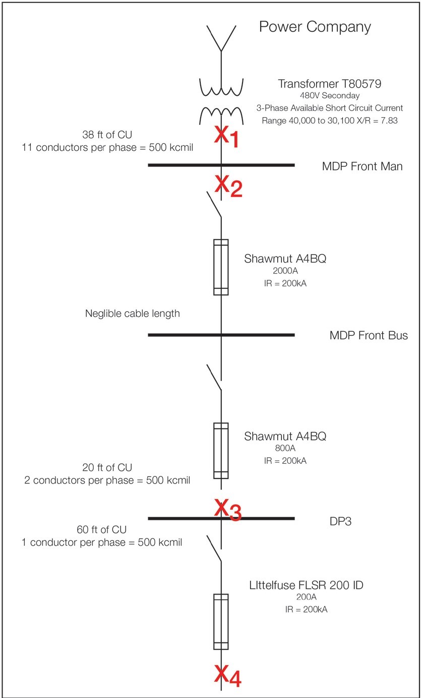 o make sure that your VFD installation meets the proper standards (i.e. the VFD panel’s SCCR exceeds the available fault current at its input) a survey of the total circuit from source to VFD is necessary.
Start by drawing a single line drawing of the circuit from the source, usually a power company transformer, all the way through to the VFD panel. Include any and all power circuit devices, such as transformers, fuses, and breakers.
This drawing will help you determine the potential fault current your VFD panel can possibly encounter at the input of the panel. Since the impedance of the conductors will also lower available fault current, the length and gauge of the conductors between power devices should be documented.
Next, layout all the components in the VFD panel, again including any fuses or MCCBs but also anything that would be in the faulted current path if the VFD output were bolted (all three phases shorted together) or the DC Bus
were shorted. To determine the total SCCR of any industrial panel, NEC allows either actual testing of the panel, which is expensive and time consuming, or calculation of the SCCR using UL508A Supplement SB methods. So that’s
a win for us. We won’t have to destroy a bunch of panels trying to find out which SCCR level the panel can successfully withstand. Instead we can:
- Establish the SCCR rating of all of the power and protective components within our panel based on their labeling. Mark the control components with their SCCR and the protective components with their AIC.
- Check if any current-limiting devices, like MCCBs and fuses, may modify the actual SCCR of any of the branches in the panel
- Figure out which is the lowest SCCR (weakest link) of any of the branches or devices and that is the VFD panel’s
- Note any and all conditions of
If the available fault current at the entrance to the panel is lower than worst case device SCCR, then the panel is safe to be energized. If the panel’s SCCR is lower than the available fault current, there are ways to increase its rating by changing protective devices. For instance adding current-limiting fuses with a lower let-though current rating can vastly increase the panel’s overall SCCR.
Example
 Let’s look at an example of how these calculations might roll out in an actual real world circuit.
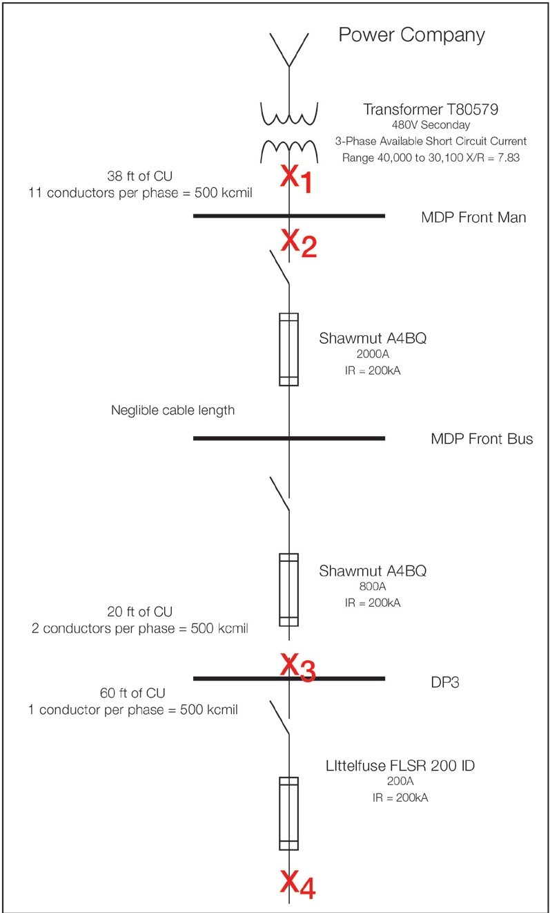
The single line drawing at left is for one of the training lab panels at Yaskawa America, Inc.’s headquarters in Waukegan, IL. The starting point is the secondary of power company’s supply transformer with a secondary voltage of 480Vac and a fault current rating of 40 kA from a 3rd party Arc Flash report.
The path to where a VFD panel would connect goes through three different fused disconnects of steadily lower ratings (2000 -> 800 -> 200 amps) but with identical 200kA IR values. Also included in the single line drawing is information about the cabling between devices.
Our first task is to determine the available fault current at the point where we want to connect our new VFD panel, X4.
As already stated, the available fault current directly at secondary of the transformer is 40,000 amps. However, due to the impedance of the cables between the transformer, mains, and distribution panel, by the time we reach the point where the VFD will be connected, the available fault current has dropped to 27,066 amps.
Therefore our VFD panel should have an SCCR rating at least 28kA or higher.
During the fault current calculations, any current limiting devices such as the fuses between the transformer secondary and the VFD panel are ignored. Where they may come into play is when we determine the necessary SCCR of our panel.
In our single line drawing, there are three current-limiting fuses in the circuit if a short circuit event happens at our VFD panel. Selective Coordination between fuses will cause only the fuse closest to the faulted circuit to open while the upstream fuses remain unopened. To achieve selective coordination between
fuses of a modern design, a ratio of 2:1 or greater in amp ratings must be maintained between adjacent fuses. In our circuit the ratios are 2.5:1 and 4:1, so we are okay.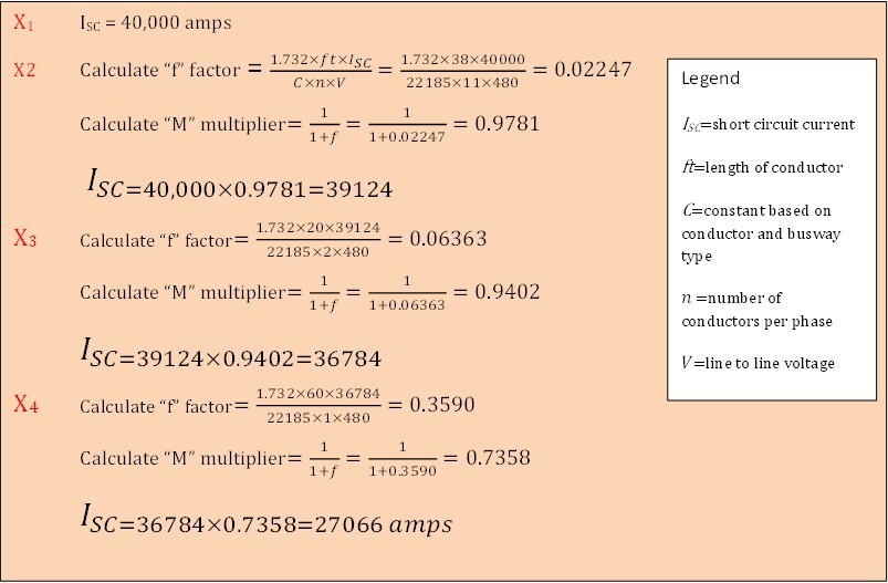
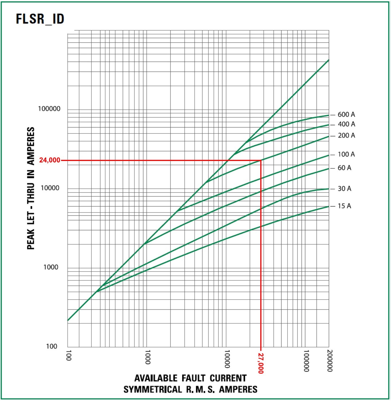
This leaves us with the Littelfuse FLSR 200 as our current limiting device. To determine the actual Let-Thru current, we will need
to consult the manufacturer’s Peak Let-Thru curves published for this series of fuse. By using the 27,066 amp fault current we determined earlier, we can determine that our 200 amp Littelfuse will allow about 24kA let-through. So whatever the weakest link device is in our VFD panel it must be greater than 24kA.
 Most VFD manufacturers will list their device SCCR ratings when installed with a manufacturer recommended protective device, usually a semiconductor fuse. Therefore the VFD’s may have very high SCCR ratings, like 65kA or 100kA, which is primarily due to the ability of the fuse to achieve rapid quenching of any fault based energy release. With such high SCCRs it should not be a problem for our VFD panel to safely be applied to our circuit. However, if other devices such as bypass contactors or motor overload devices are also in the panel, it may change “the weakest link” rating of the panel and require reanalysis of the panel’s ultimate SCCR.
Conclusion
We care about the Short Circuit Current Ratings of our panels because dangerous events can result if our panel is not adequately protected against potential fault currents. If we know what our worst case fault current level is then we can verify whether the AIC of our protective devices can safely operate at this level. You can rest assured that if the SCCR of the devices in our VFD panel are equal to or greater than available fault current, the VFD panel can safely withstand any short circuit event within the panel. By looking for the weakest link in our panel and by using current-limiting devices to lower the available fault current allowed through, we can assure ourselves that our panel is safe for a worst case short circuit event.
https://www.yaskawa.com/links?type=documents&docnum=WP.AFD.24&name=


