Ring Drives: Overcoming the Limitations of Traditional Rotary Indexing Technologies

May 31, 2019
Rotary indexing tables have been a mainstay of automation systems for decades. They are simple, precise, reliable and durable. They can output a lot of product in a relatively small footprint and with a minimal number of parts fixtures.
A rotary indexing table consists of a circular steel plate and a drive for turning it. Parts rest in nests spaced equally along the table’s circumference. Self-contained machines and tooling for specific tasks are arrayed around the perimeter. As the table rotates, it stops intermittently to “dwell” for a fixed period of time, so that an operation can be performed at each station.
Rotary indexing tables work well with machines that perform simple, fast, vertical operations, such as presses, screwdrivers, riveters, dispensers, pad printers, SCARA robots, pick-and-place units, and ultrasonic welders. Parts can be loaded and unloaded manually or automatically.
The size of a rotary indexing table depends on the product to be made and the number and type of stations needed to make it. For automated assembly applications, tables typically range in size from 18 to 100 inches in diameter.
Besides boosting output, indexing tables improve safety. Hazardous operations can be placed on the opposite side of the table from the operator. A light curtain or safety glass installed above the table, along its diameter, will ensure that the hazardous operation and the operator remain separated.
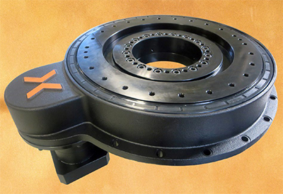
Nexen’s CRD Rotary Indexers have an IP65-rated sealed housing and come in three con-figurations, enabling the device to be optimized for high speed, high torque or both, depending on the application.
Drive Styles
There are many options for driving a rotary indexing table, including pneumatic cylinders, belts, cams, worm gears, direct-drive systems, and the latest technology—precision ring drive systems.
Pneumatic tables are best-suited for small loads, slow speeds and low production volumes. This type of table is powered by one or two pneumatic cylinders, depending on the load. Each cylinder actuation represents one index. A pawl mechanism locks the table in place during the cylinder’s return stroke. In some models, this mechanism can be adjusted to change the number of indexes. In general, however, this type of system is not that flexible and requires significant maintenance.
Belt-driven rotary tables offer the advantages of high speed and low cost. Belts are typically made of a fiber-reinforced elastomer and contain teeth that interface with rotor pulleys to efficiently transfer torque from an electric motor. Typical
belt-driven tables offer speeds up to 1,000 rpm, continuous torque to 6.6 newton- meters, and resolution down to 0.16 arc-second using ring encoders.
Belt-driven systems generate relatively little noise and they require relatively little maintenance. However, due to the potential for elongation of the belt, positioning accuracy of belt drives is often inferior to other technologies. They also have limited load capacity, limited rigidity and relatively poor life.
With a cam-driven table, the cam controls the number of indexes, as well as the acceleration, deceleration and velocity of each index. Usually, one rotation of the cam provides one dwell and one index. Constant contact between the cam and its followers means that a cam-driven indexer provides fast settling times and stiff positioning during dwell periods. Low maintenance and superior life are among the biggest benefits of cam-driven indexers. When maintenance is required, advanced skills are not needed.
The biggest drawback of cam-driven systems is inflexibility. If additional indexing positions are needed, the cam must be changed, which can be a significant expense. As a result, cam-driven machines are best reserved for long, stable production runs at high volumes.
With a table driven by a worm gear, the index characteristics are controlled directly by the motor. Worm gears are available in gear ratios ranging from 10-to-1 to 360-to-1. The advantage of a worm-gear drive is that the table can stop at any location within the rotation of the gear. In addition, worm gear systems cannot be back-driven, which is advantageous in applications where braking is required.
On the downside, worm gear systems have speed limitations, and periodic backlash adjustment may be required based on use and accuracy requirements. Worm gear systems are less efficient than other drive systems. And, if the speed reduction ratio is large, the worm gear will generate a lot of heat. As a result, these systems require constant lubrication.
One more option is a direct-drive rotary table. In this design, a permanent magnet servomotor is built into the machine itself. The motor is connected directly to
the load. There’s no need for gearboxes, worm-gear drives, or other mechanical transmission elements. That makes direct-drive rotary tables highly efficient.
Because the load is directly coupled to the drive, high accuracy is possible. With a high-line-count encoder, system resolution below 1 arc-sec is achievable with a direct-drive system.
But, direct-drive systems have numerous disadvantages. Output torque is typically low, so a very large motor is required to handle heavy loads. They are also expensive, and their accuracy is relatively low without costly ring encoders. Direct- drive systems have a larger footprint than other systems. Direct-drive motors generate a lot of heat, so a cooling system may be required. They are difficult to adjust or repair, and complex servo tuning is required.
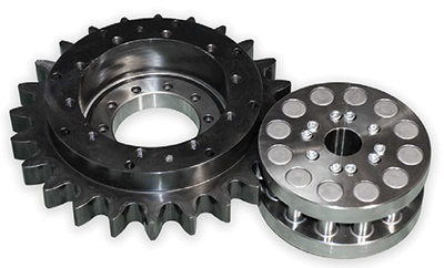
Nexen’s Rotary Indexer System is based on the company’s innovative Roller Pinion System (RPS) for linear motion. To create a Rotary Indexer, the linear rack becomes a circular Instead of moving a linear rack side to side, the pinion rotates the gear. The piniogneiasr. equipped with bearing-supported rollers that engage a unique tooth profile in the gear, providing smooth rolling friction instead of sliding friction.
A New Technology
The latest technology for rotary positioning is the Rotary Indexer System from Nexen. Based on the company’s innovative Roller Pinion System (RPS) for linear motion, Rotary Indexers come complete with a precision-grade, high-capacity bearing and drive mechanism in a rigid housing. With options for high speed, high torque and zero backlash, Rotary Indexers can be optimized for any application. With accelerations up to twice as high as other rotary indexing technologies, Nexen provides more productivity while boasting low maintenance, high efficiency and long life.
The RPS is a patented linear drive concept that combines the best attributes of existing technologies while eliminating most of their shortcomings. The RPS converts rotary motion into linear motion. The system advances the traditional rack-and-pinion concept by replacing the spur gear teeth with bearing-supported rollers that engage a unique tooth profile in the rack. Instead of the sliding friction of traditional rack-and-pinion systems, the rollers provide smooth rolling friction that converts rotary motion to linear motion with 99 percent efficiency.
The tooth profile of the rack causes the rollers to be loaded in opposition, which eliminates backlash. With this meshing geometry, each roller glides smoothly into the tooth face following a tangent path. The roller does not slap into the teeth, so there’s no noise, vibration or tooth fatigue. In addition, the RPS provides very high positional accuracy, virtually no cumulative error, low-velocity ripple, very high speeds, high rigidity, low maintenance, corrosion resistance and long life. Jams are not an issue because the pinion rollers simultaneously engage several tooth flanks in opposing directions.
To create a Ring Drive, the linear rack becomes a circular gear. Instead of moving a linear rack side to side, the pinion rotates the gear. The axis of the pinion and the axis of the gear are parallel. A servomotor can be connected directly to the pinion or it can be connected through a gearbox. A circular plate is bolted atop the gear to create a rotary indexing table.
Unlike some cam-driven rotary indexing systems, the Rotary Indexer can start and stop at any incremental position. Engineers can change the motion profile by simply loading a new servo drive program. The Rotary Indexer also allows maximum acceleration or deceleration at any point without the risk of damage.
Rotary Indexers offer numerous advantages. First, they are precise. There are
models with an indexing precision of ±11 arc-seconds and a repeatability of ±1.2 arc-
second. Unlike other mechanical drive systems, Rotary Indexers offer zero backlash options from the motor through the driven load.
Rotary Indexers offer smooth motion, high load capacity and high speed. With their precision-grade, high-capacity cross-roller bearings, Rotary Indexers can handle loads up to 1,575 kilonewtons. They can also handle speeds up to 225 rpm. Unlike traditional cam driven systems, Rotary Indexers can handle peak torque inputs at any time. This allows for indexing times up to two times faster than the competition.
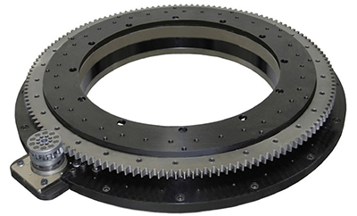
Equipped with a high-precision planetary gearhead, the PRD Rotary Indexer offers high torque, high speed, low backlash and a flexible gearhead ratio. Like the CRD Rotary Indexer, the PRD has a large, open center.
Rotary Indexers are typically mounted horizontally to carry an applied load, like any rotary indexing table. However, they can also be mounted upside down to carry a suspended load, or they can be mounted vertically. In the latter case, for example,
a Rotary Indexer can serve as a trunnion, positioning parts for robotic welding systems.
Rotary Indexers are available in two types: the Compact Ring Drive (CRD) and the Precision Ring Drive (PRD).
CRD Rotary Indexers have an IP65-rated sealed housing and come in three configurations, enabling the device to be optimized for high speed, high torque or both, depending on the application.
Equipped with a high-precision planetary gearhead, the CRD PL offers high torque, high speed, low backlash and a flexible gearhead ratio. Peak output torque can be 494, 676 or 1,066 newton-meters. Positional accuracy ranges from ±27 to
±59 arc-seconds. Maximum backlash ranges from 9.4 to 20.3 arc-seconds. With a planetary gearbox ratio of 4-to-1, input to output speed ratio ranges from 15.2-to- 1 to 32.8-to-1.
Equipped with a harmonic gearhead, the CRD HG offers high torque, low speed, zero backlash and a high gearhead ratio. Peak output torque can be 532, 728 or 1,148 newton-meters. Positional accuracy ranges from ±20 to ±43 arc-seconds. With a harmonic gearhead ratio of 50-to-1, input to output speed ratio ranges from 190-to-1 to 410-to-1.
Equipped with a direct-drive pinion, the CRD DD offers high speed, medium torque and zero backlash. The motor is integrated into the system, and it does not have a gearhead. Peak output torque can be 367, 497 or 770 newton-meters. Positional accuracy ranges from ±20 to ±41 arc-seconds. Input to output speed ratio ranges from 6.2-to-1 to 13-to-1.
CRD 3PUBSZ *OEFYFST have a large, open center, so engineers can mount equipment and cabling in the center of the rotating plate. The output plate of the CRD 250
has an inner diameter of 115 millimeters, an outer diameter of 290 millimeters, and a circle of bolt holes 250 millimeters in diameter. The output plate of the CRD 350 has an inner diameter of 155 millimeters, an outer diameter of 385
millimeters, and a circle of bolt holes 350 millimeters in diameter. The output plate of the CRD 550 has an inner diameter of 350 millimeters, an outer diameter of 600 millimeters, and a circle of bolt holes 550 millimeters in diameter. An optional zero-backlash holding brake is available for the CRD 250 that acts directly on the driven output. The brake is spring engaged and pneumatically released, so it will default to lock in the event of a power failure or emergency situation. The brake’s compact design does not increase the footprint of the Rotary Indexer and still maintains an open center (31.7 millimeters in diameter vs. 115 millimeters without the brake). The brake can hold loads up to 800 newton meters.
Rotary Indexers offer smooth motion, high load capacity and high speed. With their precision-grade, high-capacity cross-roller bearings, Rotary Indexers can handle loads up to 1,575 kilonewtons.
Equipped with a high-precision planetary gearhead, the PRD offers high torque, high speed, low backlash and a flexible gearhead ratio. Like the CRD, the PRD has a large, open center.
It comes in four sizes. The output plate of the PRD 400 has an inner diameter of 280 millimeters, a minimum outer diameter of 550 millimeters, and a circle of bolt holes 396 millimeters in diameter. The output plate of the PRD 750 has an inner diameter of 600 millimeters, a minimum outer diameter of 900 millimeters, and a circle of bolt holes 750 millimeters in diameter. The output plate of the PRD 1100 has an inner diameter of 950 millimeters, a minimum outer diameter of 1,350 millimeters, and a circle of bolt holes 1,100 millimeters in diameter. The output plate of the PRD 1500 has an inner diameter of 1,330 millimeters, a minimum outer diameter of 1,750 millimeters, and a circle of bolt holes 1,500 millimeters in diameter.
Peak output torque can be 832, 1,430, 2,210 or 2,860 newton-meters. Positional accuracy ranges from ±11 to ±35 arc-seconds. Maximum backlash ranges from 3 to 12 arc-seconds. With a planetary gearbox ratio of 4-to-1, input to output speed ratio ranges from 25.6-to-1 to 88-to-1. The PRD Rotary Indexer has a shrouded housing.
When specifying a rotary indexer, engineers should consider work table diameter; through-hole diameter; speed; acceleration; load inertia; index time; index distance; maximum dynamic axial load; maximum dynamic radial load; maximum dynamic moment load; maximum static axial load; maximum static radial load; maximum static moment load; shock factor; and drag torque and other applied torque loads, such as table support friction or clamping forces. Engineers
should also delineate the minimum and maximum indexing increments, the environmental conditions of the application, positional accuracy requirements, and mounting orientation.
For more information on the Roller Pinion System, call the Nexen Group 800-843-7445 or visit www.nexengroup.com.


