Facts Worth Knowing About AC Drives – Electric Motors Sections 2.1 – 2.3.6
May 5, 2020
Electric Motors
2.1 Overview
An electric motor is an electromechanical device that converts electrical energy into mechanical energy. The reverse process of producing electrical energy from mechanical energy is performed by a generator.
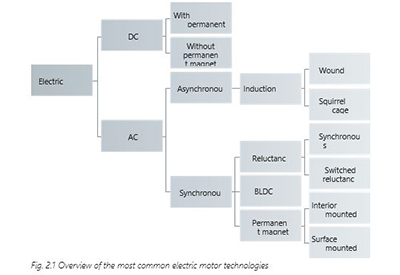
The operating demands of the electric motor, especially in industry, have been enormous. Robustness, reliability, size, energy efficiency, and price are only some of these criteria. The differing needs have resulted in the development of different types of electric motors. The following diagram gives a general overview of the most commonly used electric motor technologies.
2.2 Fundamentals
2.2.1 Stator and Rotor
The construction of all rotating electric motors consists in principle of two main components.
Stator
The stator (1) is the stationary part of the motor which holds packages of laminations where the electrical windings are placed.
Rotor
The rotor (2) is the rotating part of the motor which is mounted on the motor shaft. Like the stator, the rotor is made of thin iron laminations which hold the rotor windings.
One variation is the outer rotor motor. Unlike the inner rotor design, the stator is placed in the middle of the motor and the rotor rotates around the stator. This construction is used in some fan applications where the fan blades are directly mounted on the rotor. Unless otherwise mentioned, all the following explanations are related to inner rotor design.
The connection dimensions of typical industrial motors are defined in IEC standards. However not all motors fulfill these requirements. For example, NEMA frame motor dimensions differ from IEC standards, due to the conversion from the metric to the imperial system.
2.2.2 Power and Torque
The rated output of electric motors is defined within a standard range. This standardization allows users to choose between different motor manufacturers for specific applications. The “standard” output range and its increments differ from country to country and region to region. It is recommended to find out what manufacturers define as standard in their catalogues. On average, motors with frame size up to 355 (ca. 400 kW) can be regarded as standard motors with standard dimensions.
Horsepower [hp] is the imperial unit used for motor power. If this unit is specified, it can be converted as follows: 1 hp = 0.736 kW or 1 kW = 1.341 hp.
Table 2.1 shows the typical industrial standard rated output power in [kW] and [hp].
Besides power, torque is an important characteristic of the motor. Torque indicates the strength of rotation of the motor shaft. Power has a direct relationship to torque and can be calculated when torque and speed are known.
P = T × (2 × π × n) ≈ (T × n)
60 × 1000 9550
P = Power [kW] T = Torque [Nm] n = Speed [RPM]
The factor 9550 used in the formula results from the conversion of units:
- – Power from the base unit W (watt) to nameplate unit kW (kilowatt)
- – Speed from the base unit rad/s (radians per second) to s-1 (revolutions per second), and then to nameplate min-1 (revolutions per minute)
2.2.3 AC and DC Motors
The first electric motor, a DC motor, was built around 1833. Speed control of this type of motor is simple and met the requirements of many different types of applications at the time. The DC motor is controlled by supplying a DC voltage whose magnitude influences the speed of the rotor. Voltage applied to stator and rotor windings results in magnetic fields which attract or repel each other, leading to rotor movement.
Energy supplied to the rotor is transmitted via brushes, typically made of graphite, to a commutator. The commutator ensures that the next winding is energized to achieve a continuous rotation. The brushes are subject to mechanical abrasion and require maintenance or periodic replacement. The importance of DC motors has decreased over time and they are rarely used in power ranges above a few hundred watts today.
Compared to DC motors, AC motors are much simpler and more robust. However, AC motors typically have a fixed speed and torque characteristic. Because of these fixed characteristics, for many years AC motors could not be used for many diverse or special applications. They are nonetheless used in most applications to transform electrical energy into mechanical energy.
The functional principle of AC motors is based on the effects of a rotating magnetic field. The rotating field is generated either from a multi-phase fed AC source (typically three-phase) or from a single-phase source assisted by capacitors or inductances to achieve phase shift.
This book focuses on AC motors, particularly on induction motors, as the requirements for operation with AC drives in adjustable speed drive applications for various motor types can be derived from this motor technology. DC motors will not be addressed further.
2.2.4 Electromagnetic Induction
Most electric motors operate through the interaction of magnetic fields and current- carrying conductors to generate force. This is the reverse process of producing electrical energy from mechanical energy, performed by generators such as an alternator or a dynamo on a bicycle.
a) Generator principle, induction by motion
When a force (F) acts on a conductor and moves it across a magnetic field (B), a voltage is induced. If the conductor is part of a closed circuit, a current (I) flows, see Fig. 2.3 Principle for electromagnetic induction.
b) Motor principle
In motors, the induction principle is utilized in the reverse order: a force (F) is generated which will act on the current-carrying conductor, causing movement.
Left: Generator principle Right: Motor principle

In both cases a magnetic field is required. In Fig. 2.3 Principle for electromagnetic induction the magnetic field originates from a permanent magnet, but in a motor the magnetic field is
generated in the stator. Typically, this is achieved by applying voltage to the stator windings. The conductors affected by the electromagnetic force are located in the rotor.
2.2.5 Poles, Synchronous Speed and Asynchronous Speed
The synchronous speed of a motor can be calculated when the supply frequency and number of pole pairs are known.
n₀ = f ´ 60
p
f = frequency [Hz]
n₀ = synchronous speed [min-1]
p = pole pair number
While the frequency is determined by the grid or the AC drive, the number of poles is determined by the way the stator Inductors are connected.
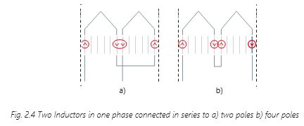
Table 2.2 Pole pairs (p) or pole number and synchronous motor speed – lists the number of poles corresponding to synchronous speed (n0) at 50 and 60 Hz supply. Higher pole numbers are possible but rarely used nowadays.
Synchronous means “simultaneous” or “the same”. This means in synchronous motors the speed of the rotor is the same as the speed of the rotating field. If the rotor speed is affected by slip (see also section 2.3.3 Slip, Torque and Speed) and therefore lower than the speed of the rotating field, the motor is classified as asynchronous, meaning “not simultaneous” or “not the same”.

2.2.6 Efficiency and Losses
The motor draws electrical power from the mains. At a constant load, this power is greater than the mechanical power the motor can output to the shaft, due to various losses in the motor. The ratio between the output power P2 and input power P1 is the motor efficiency:
η = P2 = output power
P1 input power
The efficiency depends on the motor principle, components (for example lamination quality), amount of active material (for example, due to lamination or use of magnets), size of the motor (rated power) and number of poles.
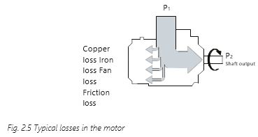
The losses in the motor are illustrated in Fig. 2.5 Typical losses in the motor. The typical losses comprise:
- – Copper losses because of the resistances of the stator and rotor windings
- – Iron losses consisting of hysteresis losses and eddy-current losses
Hysteresis losses occur when iron is magnetized by an alternating current (AC).
The iron is magnetized and demagnetized repeatedly (that is, 100 times per second with a 50 Hz supply). Magnetizing and demagnetizing both require energy. The motor supplies power to cover the hysteresis losses, which increase with frequency and the strength of magnetic induction.
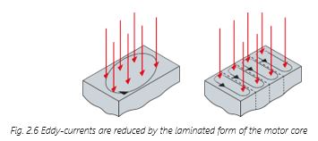
Eddy-current losses occur because the magnetic fields induce electric voltages in the iron core as in any other conductor (see Fig. 2.6 Eddy-currents are reduced by the laminated form of the motor core). These voltages produce currents that cause heat losses. The currents flow in circuits at right angles to the magnetic fields.
The eddy-current losses are dramatically reduced by dividing the iron core into thin laminations.
- – Fan losses occur due to the air resistance of the motor fan
- – Friction losses occur in the ball bearings holding the rotor
When determining the efficiency and motor output power, the losses in the motor are normally subtracted from the supplied power. The supplied power is measured, whereas the losses are often calculated or determined experimentally.
2.3 Induction Motors
To understand clearly how an adjustable speed drive system works, it is necessary to understand the principles of operation of this type of motor. Although the basic design has not changed much in the last decades, modern insulation materials, computer-based design optimization techniques as well as automated manufacturing methods have resulted in lower cost per kilowatt power and higher efficiency for a given motor frame size.
The information in this book will apply mainly to the so-called “squirrel-cage“ three-phase induction motor, which is the type commonly used with AC drives.
2.3.1 Rotating Field

The magnetic field in the stator core has a fixed location, but its direction varies, as shown in Fig. 2.7 above. One phase produces an alternating field. The speed of rotation is determined by the supply frequency. At a frequency of 50 Hz, the field changes direction 100 times per second (two times per period).

If two phase windings are connected to the respective supply phases, two magnetic fields are induced in the stator core. In a two-pole motor, one field is displaced by 120 degrees relative to the other. The maximum field values are also displaced in time, as shown in Fig. 2.8 Two phases produce an asymmetrical rotating field.
This produces a rotating magnetic field in the stator which is highly asymmetrical until the third phase is connected. When the third phase is connected, there are three magnetic fields in the stator core. There is a 120° displacement between the three phases, as shown in Fig. 2.9 Three phases produce a symmetrical rotating field.

The stator is now connected to the three-phase supply. The magnetic fields of the individual phase windings form a symmetrical rotating magnetic field. This magnetic field is called the rotating field of the motor.
The amplitude of the rotating field (φ) is constant and 1.5 times the maximum value (jmax) of the alternating fields. It rotates at the synchronous speed resulting from the pole pair number and supply frequency (see also section 2.3.3 Slip, Torque and Speed).
The representation of the rotating field as a vector with a corresponding angular velocity describes a circle, shown in Fig. 2.10 Magnetic field components. The magnitude of the magnetic field φ as result of the components (φ1, φ2, φ3) is constant also at different moments (a and b). Three sinusoidal fields with a 120-degree phase-shift make up a circular rotating magnetic field. The rotating field becomes elliptical if the amplitude changes during a rotation.
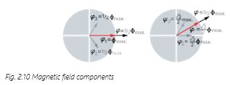
With single phase motors the phase shift which determines the rotation direction of the motor is created by a capacitor or an inductance which also results in an elliptical field.
2.3.2 Squirrel-cage Motor
The squirrel-cage rotor is the most frequently-used rotor type and is used in the squirrel-cage motor. Unlike the stator, where the inductors have many windings, in the squirrel-cage motor, only one winding is placed in the slots of the rotor lamination. This is typically done with aluminum or copper rods. The rods are short-circuited at each end of the rotor by a ring made of the same material. Copper has the advantage that it has a better conductivity than aluminum which results in lower losses and a higher efficiency. Drawbacks compared to aluminum are higher prices, lower starting torques and higher melting temperature which complicate the casting and leads to a higher tooling effort.

A variant of the squirrel-cage rotor is the slip-ring rotor which has wound inductors for each phase. The inductors are connected to slip-rings. Brushes sliding on the slip-ring allow the connection of external resistors which modifies the motor behavior (see also section 2.3.5 Changing Speed). If the slip-rings are short-circuited, the rotor acts as a squirrel- cage rotor.
The rotor movement of the squirrel-cage motor is created as follows:
A rotor rod placed in the rotating field is passed by a series of magnetic poles, as shown in Fig.2.11 above.
The magnetic field of each pole induces a current (IW) in the rotor rod, which is influenced by a force (F). This force is determined by the flux density (B), the induced current (IW), the length (L) of the rotor within the stator, and the angle (θ) between the force and the flux Assuming that θ = 90°, the force is:
F = B ´ IW ´ L
The next pole passing the rod has an opposite polarity. It induces a current in the opposite direction to the previous one. Since the direction of the magnetic field has also changed, the force acts in the same direction as before as shown in Fig. 2.12b Induction in the rotor rods.
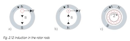
When the entire rotor is located in the rotating field, see Fig. 2.12c Induction in the rotor rods, the rotor rods are affected by forces that cause the rotor to rotate. The rotor speed (2) does not reach the speed of the rotating field (1) since no currents are induced in the cage bars when it is rotating at the same speed as the field.
2.3.3 Slip, Torque and Speed
As described in sections 2.2.5 Poles, Synchronous Speed and Asynchronous Speed and 2.3.2 Squirrel-cage Motor, under normal circumstances the rotor speed (nn) of induction motors is slightly lower than the speed (n0) of the rotating field. The difference between the speed of the rotating field and the rotor is called slip (s) where:
sa = n₀ – nn
The slip is often expressed as a percentage of the synchronous speed and is typically between 1 and 10 percent.
s = n0 a – nn x 100%
n0
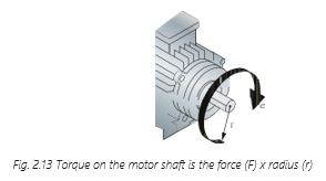
The individual forces in the rotor rods combine to form the torque (T) on the motor shaft (see section 2.3.2 Squirrel-cage Motor). With a given value of force (F) and radius (r) the motor torque is: T = F ´ r.
The relationship between motor torque, speed and current of induction motors has a characteristic curve, shown in Fig. 2.14 Principal motor current and torque characteristics. This curve depends on the rotor slot design and the rod material.
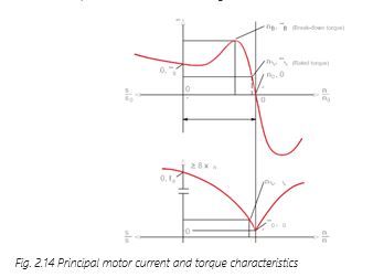
The motor operating range (0 < n/n0 < 1) can be split up into two ranges:
- – Starting range (0 < n/n0 < nB /n0)
- – Operating range (nB /n0 < n/n0 < 1)
These ranges have the following characteristics:
Starting torque TS. This is the torque the motor produces with the rated voltage and rated frequency applied at standstill.
Stall torque TB at stall speed nB. This is the highest torque the motor can produce when the rated voltage and rated frequency are applied.
Rated motor torque Tn at nominal speed nn.
The rated values of the motor are the mechanical and electrical values for which the motor was designed in accordance with the IEC 60034 standard. The rated values, also called motor specifications or motor ratings, are stated on the motor nameplate.
The rated values indicate the optimal operating point for the motor, when connected directly to the mains.
Apart from the normal motor operating range, there are two braking ranges.
- – n/n0 > 1: the motor is driven by the load above its synchronous speed (n0) operating as a generator. In this region, the motor produces a counter torque and simultaneously returns power to the supply
- – n/n0 < 0: braking is called regenerative braking or
If two phases of a motor are suddenly interchanged, the rotating field changes direction. Immediately afterwards, the speed ratio n/n0 is 1. The motor, previously loaded with torque T, now brakes with its braking torque. If the motor is not disconnected at n = 0, it will continue to run in the new rotational direction of the magnetic field.
2.3.4 Typical Operating Conditions
In principle, induction motors have six inductors: three inductors in the stator and three inductors in the squirrel-cage rotor (which behaves magnetically as if it consisted of three inductors). A subset of these inductors can be used as the basis for generating an equivalent circuit that makes the operating principle of the motor easier to understand, especially when the frequency of the supply voltage changes.

Applying a supply voltage (U1) results in a current in the stator (I1) and the rotor (I2) which is limited by the resistance in stator (R1) and rotor (R2) and the reactance in stator (X1σ) and
rotor (X2σ). While the resistance is independent of the supply frequency the reactance has an influence.
XL = 2 x π x f x L
XL = reactance
[Ω] f = frequency
[Hz] L = inductance [H]
The inductors mutually influence each other by means of magnetic induction. The rotor inductor induces a current in the stator inductor and vice versa. This mutual effect means that the two electric circuits can be interconnected via a common element consisting of RFe and Xh, which are called the transverse resistance and reactance. The current the motor draws for magnetizing the stator and the rotor flows through this common element. The voltage drops across the ”transverse link” is the induction voltage (Uq). As RFe is very small and is neglected in the following explanations.
Standard operation
When the motor operates in its normal operating range, the rotor frequency is, due to the slip, lower than the rotating field frequency. In the equivalent circuit diagram, the effect is described by a change in the rotor resistance R2 by the factor 1/s. R2/s can be expressed as
R2 + R2 ´ (1 – s)/s where R2 ´ (1 – s)/s represent the mechanical motor load.
No-load situation
The slip s is small at no-load (idle) operation. This means that R2 ´ (1 – s)/s is high. Consequently, almost no current can flow through the rotor. Ideally, this is comparable to removing the resistor that represents the mechanical load from the equivalent circuit.
The induced voltage (Uq) is often confused with the motor terminal voltage. This is due to the simplification of the equivalent circuit diagram to make it easier to understand various motor conditions. However, the induced voltage only approximately corresponds to the terminal voltage in no-load operation.
Locked rotor situation
The slip increases when the motor is operating under load. Therefore, R2 ´ (1 – s)/s will decrease. When the rotor is locked the slip is 1 and hence the current which increases with the load reaches its maximum.
The equivalent circuit diagram thus corresponds to the conditions applicable to the induction motor in normal practice. It can be used in numerous cases for describing conditions in the motor.
2.3.5 Changing Speed
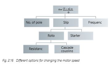
The motor speed n is dependent upon the rotational speed of the magnetic field and can be expressed as:
n = n0 – ns = (1 – s) ´ f
p
The motor speed can therefore be changed by changing:
- – The pole pair number p of the motor (for example, pole-changing motors)
- – The motor slip s (for example, slip-ring motors)
- – The motor supply frequency f (for the motor)
Pole number control
The rotational speed of the magnetic field is determined by the number of pole pairs in the stator. In the case of a two-pole motor, the rotational speed of the magnetic field is 3000 RPM at a motor supply frequency of 50 Hz. For a four-pole motor the speed is 1500 RPM.
Motors can be designed to have two or more different pole-pair numbers. This is done by using a special arrangement of the stator windings (Dahlander winding) in the slots and/or by using more separate and isolated windings in the slot.
The speed is changed by switching the stator windings to change the number of pole pairs in the stator. By switching from a small pole-pair number (high speed) to a high pole-pair number (low speed), the actual motor speed can be dramatically reduced, for example, from 1500 to 750 RPM. With rapid switching from higher to lower speed, the motor runs through the regenerative range. This places a considerable load on the motor and the mechanism of the driven machine which can cause damage to motor and machinery.

Slip control
Controlling the motor speed using slip can take place in two different ways: either by changing the stator supply voltage or by modifying the rotor. It should be mentioned that these methods involve considerable thermal losses. Please refer to other sources of information if more is needed.
Rotor control
Controlling the motor speed using the rotor can be made in two different ways:
- – Resistors are inserted in the rotor These types of motors are called “slip-ring” motors. The trade-off using this method is higher power losses in the rotor circuit.
- – Rotor circuits are cascaded with other electrical machines or rectifier circuits. The rotor circuit is then connected via slip rings to DC machines or to controlled rectifier circuits instead of resistors. The DC machine supplies the rotor circuit with additional variable voltage making it possible to change the rotor speed and
Frequency regulation

With a variable frequency supply, it is possible to control the motor speed with minor additional losses. The rotational speed of the magnetic field and hence the rotor speed changes with the frequency. To maintain the motor torque, the motor voltage must change together with the frequency as shown in Fig. 2.18 Torque characteristics with voltage/frequency control.
At low speed the ratio must be adjusted to compensate for the ohmic losses. Further forced cooling may be required in this speed range.
2.3.6 Motor Nameplate and Star or Delta Configuration
Normally the motor has a nameplate on it which has all essential motor data. Additional data are available in the motor catalogue or can be obtained from the manufacturer.
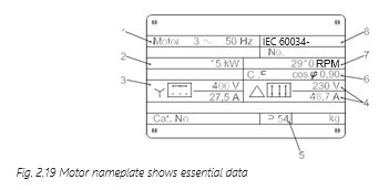
The nameplate shown has the following information:
- 1. It is a three-phase AC motor with a rated frequency of 50 Hz
- 2. Rated output (shaft) power is 15 kW
- 3. The stator windings can be connected in series (star) with a rated voltage of 400 V and rated (apparent) current of 27.5 A
- 4. Alternatively, the stator windings can be connected in parallel (delta) with a rated voltage of 230 V and rated (apparent) current of 48.7 A
- 5. It has an IP 54 protection
- 6. Insulation class F (155 °C) and a power factor (cos φ) of 0.90.
- 7. Rated speed 2910 RPM (a two-pole motor) is the motor speed at the rated voltage, rated frequency and rated load
- 8. Fulfils the IEC 60034-6 standards
Some motor data (torque, efficiency, etc.) can be calculated using the nameplate data. For example, the power factor can be used to calculate the active and reactive components of the motor current.
Pay special attention to the rated motor voltages in star and delta. If the supply voltage is higher than the rated voltage of the applied configuration, the motor will be damaged. The connection itself can be often changed by rearranging the jumpers at the motor terminal.
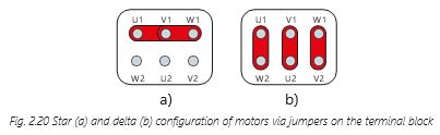
In delta connection the full supply voltage (phase-to-phase voltage, Upp) is applied to each motor phase but the phase current (Ip) is reduced by the factor √3. In star connection the current is maintained, and the phase voltage (Up) is reduced. Therefore, the power is the same regardless of the connection since the feeding voltages are different.
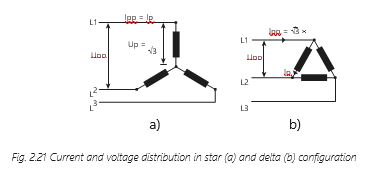
In a delta connection Upp = Up, so the motor must suit the supplying mains. This means that on 400 V mains the motor must have a 690 V star and a 400 V delta rating. So-called star/delta starters utilize this behavior for reducing the starting current of a motor. At start the motor will be connected in a star, reducing current, power and torque to one-third. After the motor has been accelerated the connection will be changed to delta.
Motor voltages in catalogues are often expressed by mentioning the star and delta voltages together (example: 400/230 V Y/Δ or 690/400 V Y/Δ). The voltages are phase-to-phase voltages. Therefore, the lower voltage is always related to delta and the higher to the star connection.
The relation of the current is vice versa: the lower current relates to the star configuration and the higher current relates to the delta configuration.