Facts Worth Knowing about AC Drives – AC Drives Sections 3.8 – 3.9.2
July 8, 2020
3.8 Danfoss Control Principles
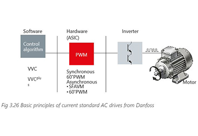
A general overview of the standard current control principles for Danfoss AC drives is illustrated in Fig. 3.26 Basic principles of current standard AC drive from Danfoss.
The PWM switching patterns are calculated for the inverter using the selected control algorithm. U/f control is suitable for applications involving
- – Special motors
- – Motors connected in parallel
In the case of the applications referred to above, no compensation of the motor is required. With the VVC+ control principle, the amplitude and angle of the voltage vector are controlled directly, as is the frequency. At the heart of this method lies a straightforward, yet robust, motor model. The type of control method involved is called Voltage Vector Control (VVC).
Some of the features offered include:
- – Improved dynamic properties in the low speed range (0 – 10 Hz)
- – Improved motor magnetization
- – Speed control range: 1:100 open loop
- – Speed accuracy: ±0.5% of the rated speed without feedback
- – Active resonance dampening
- – Torque control
- – Operation at the motor current limit
3.8.1 Danfoss VVC+ Control Principle
The Danfoss VVC+ control principle uses a vector modulation method for constant voltage- source PWM inverters. Depending on the application control demands, the motor equivalent diagram can be simplified (that is, the iron, copper and air flow losses are ignored) or used in its full complexity.
Example:
A simple fan or pump application control uses a simplified motor diagram. However, a dynamic hoist application requiring flux vector control requires the complex motor equivalent diagram, accounting for all losses in the control algorithm.
The inverter switching pattern is calculated using either the SFAVM or 60° AVM principle, to keep the pulsating torque in the air gap very small. The user can select the preferred
operating principle or allow the control to select one automatically on the basis of the heatsink temperature. When the temperature is below 75° C, the SFAVM principle is used for control. At temperatures above 75°, the 60° AVM principle is applied.
The control algorithm takes two operating conditions into consideration:
- – No-load state (idle state), see Fig. 3.27a Motor equivalent circuit diagram under “no- load”. In the no-load state, there is no load on the motor shaft. For conveyors the no- load state literally means no products are being transported. It is simply assumed the current drawn by the motor is only needed for magnetization and compensation for losses. The active current is considered to be nearly zero. The no-load voltage (UL) is determined based on the motor data (rated voltage, current, frequency, speed).

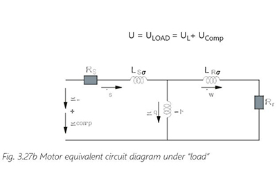
- – Loaded state: The motor shaft is loaded, implying that products are being transported, as shown in Fig. 3.27b Motor equivalent circuit diagram under “load”. The motor draws more current when it is loaded. To produce the required torque, the active current (IW) is needed. Losses in the motor (especially in lower speed range) need to be compensated for. A load-dependent additional voltage (UComp) is made available to the motor:
The additional voltage UComp is determined using the currents measured under the two conditions mentioned above (loaded and no-load) as well as the speed range: low or high speed. The voltage value and the speed range are then determined based on the rated motor data.
The control principle is illustrated in the block diagram below:
As shown in Fig. 3.28 Basic principles of Danfoss VVC+ control, the motor model calculates the no-load references (currents and angles) for the load compensator (ISX, ISY) and the voltage vector generator (I0, θ0).
The voltage vector generator calculates the no-load voltage (UL) and the angle (θL) of the voltage vector on the basis of the no-load current, stator resistance and stator inductance.

The measured motor currents (Iu, Iv and Iw) are used to calculate the reactive current (ISX) and active current (ISY) components.
Based on the calculated currents (ISX0, ISY0, ISX, ISY) and the voltage vector actual values, the load compensator estimates the air-gap torque and calculates how much extra voltage (UComp) is required to maintain the magnetic field strength at the reference value. It then corrects the angle deviation (Δθ) that is to be expected due to the load on the motor shaft. The output voltage vector is represented in polar form (p). This enables direct overmodulation and facilitates connection to the PWM.
Voltage vector control is particularly useful for low speeds, where the dynamic performance of the drive can be significantly improved (compared with U/f control) by means of appropriate control of the voltage vector angle. In addition, steady-state behavior improves, since the control system can make better estimates for the load torque on the basis of the vector values for both voltage and current than it would be able to on the basis of the scalar signals (amplitude values).

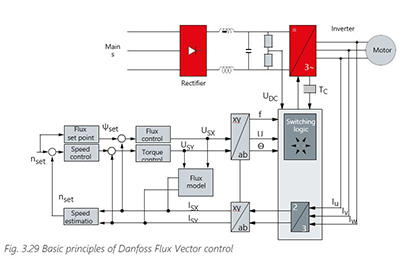
3.8.2 Danfoss Flux Vector Control Principle
The principle of flux vector control assumes that a complete equivalent circuit diagram data is available. With this approach, all the relevant motor parameters are considered by the control algorithms. Considerably more motor data needs to be specified than is the case with the basic VVC+ control.
Changing a single parameter during commissioning switches the control algorithm from VVC+ control to flux vector control. Here more information needs to be fed in to the drive for smooth control of the motor. All parameters will not be explained here as they are fully explained in the operation manuals.
A brief description of the control strategy is shown in Fig. 3.29 Basic principles of Danfoss Flux Vector control. A flux database is stored in the AC drive. The currents measured in all 3 phases are transformed in to polar coordinates (x, y).
3.9 Medium Voltage Drives
With infrastructures around the world developing and heavy industries becoming more important, the need for higher power output is growing. Motors are getting bigger in many industries and in a wide range of driven equipment. Medium-voltage AC drives are needed to satisfy the customers´ and users´ needs for AC drives in the medium and high-power range. When the required power output increases, there comes a point when it makes sense to switch from LV drives to MV drives. It is not practical nor is it economical to use LV drives in the upper power range. Above a certain power requirement there is no other choice than MV drives. The higher voltage enables lower current, fewer losses and reduced system costs.
Due to technology advancements in semiconductor devices such as IGBTs, modern MV drives are increasingly used in petrochemical, mining, steel and metal, transportation industries among others to conserve electric energy, increase productivity and improve product quality. The development of MV drives is also motivated by the improvement in the efficiency, weight and volume of the motor and in the reduced installation costs related to transformers, cable sizes, cable trays etc.
MV drives are classified to cover a power range of 0.2 MW to almost 40 MW at the MV level of 2.3–13.8 kV. However, most of the installed MV drives in industrial settings are in the range of 1–4 MW, with voltage ratings of 3.3–6.6 kV.
3.9.1 MV Semiconductors
There are different types of semiconductors used in MV drives. These include the IGBT, the integrated gate-commutated thyristor (IGCT) and the injection enhanced gate transistor (IEGT).
The most commonly used semiconductor device is the power diode, which is widely used for uncontrolled rectifiers and as a freewheeling diode in antiparallel connections with power switches.
The IGBT is the dominant technology in low-power and low-voltage applications. Nevertheless, there are drive topologies that can arrange them to reach MV operation. Recent developments have resulted in IGBTs with higher-voltage blocking capability closer to the IGCT, also known
as MV-IGBT, HV-IGBT and IEGT. Currently, the IGBT and IGCT are the most commonly used semiconductors in the market.
3.9.2 MV Drive Topologies
Research and development in MV drives has been very active during the last decade. In fact, several new commercial MV drive topologies have been introduced. The main reason for the development has been an increase in industrial processes demanding higher power, MV operation, and variable speed capability. As a result, different drive topologies have been developed to meet the requirements of different applications.
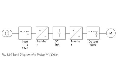
The main components of MV drives are like those used in LV drives: rectifier, DC-link, inverter and optional grid and motor side filters. The rectifier can be either controlled or uncontrolled, regenerative or nonregenerative. In addition, MV drives can be classified into two-level and multilevel converters depending on the number of voltage levels generated at the output.
Some of the most common MV drive topologies are listed below..
Three-Level Neutral-Point-Clamped Converter (3L-NPC)
The 3L-NPC uses an arrangement of four power switches per leg, clamped with diodes to a midpoint of the DC-link. Each switch blocks half of the total DC-link voltage, enabling MV operation with IGCT and HV-IGBT devices. The converter clamps the phase output to the neutral point, generating an extra voltage level compared to two-level converters.
The 3L-NPC is a simple and proven topology. The main benefits include reduced dv/dt and THD in its AC output voltages. More importantly, the inverter can be used in the MV drive to reach a certain voltage level without switching devices in series. A disadvantage of this topology is, that it requires voltage balancing of the DC-link capacitor voltages.
Cascaded H-Bridge Converter (CHB)
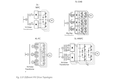
The CHB multilevel inverter is one of the most popular converter topologies used in MV drives. It is composed of multiple units of single-phase three-level H-bridge power cells. The H-bridge cells are normally connected in cascade on their AC side to increase the converter voltage and to achieve MV operation. The number of output voltage levels is 2k+1, where k is the number of cells.
Because of the high amount of output voltage levels, this converter does not require an output filter for most applications. The main drawback of this topology is the need of isolated DC sources to power each H-bridge, which requires a complicated phase-shifting transformer.
However, this transformer together with diode rectifiers forms a multipulse configuration with very low input current distortion and eliminates the need to balance capacitor voltages. Because of the complicated front end, it is uncommon to see this converter in highly regenerative applications, and the great majority feature diode front ends.
In practice, the number of power cells in a CHB inverter is mainly determined by its operating voltage and manufacturing cost. The use of identical power cells leads to a modular structure, which is an effective means for cost reduction. Due to this, commercial CHBs can be found up to 17 levels and 13.8 kV with low voltage IGBT technology. The most common configurations are the seven-level CHB at 3.3 kV and 13-level CHB at 6.6 kV.
Four-Level Flying Capacitor Converter (4L-FLC)
This topology has evolved from the two-level inverter by adding DC capacitors to the cascaded switches. There are three complementary switch pairs in each of the inverters. Each pair of switches with one flying capacitor forms a power cell. Additional cells can be connected, increasing the number of voltage levels of the converter, and the topology is therefore considered a modular structure. The FLC can produce an inverter phase voltage with four voltage levels, while reducing the voltage stress on the power switches.
However, the practical use of the FLC inverter is limited due to the use of many capacitors and a complex control scheme.
Five-Level H-Bridge NPC Converter (5L-HNPC)
The 5L-HNPC bridge inverter is developed from the 3-L NPC and CHB topologies. It is composed of two 3L-NPC legs forming an H-bridge per phase. This generates a five-level voltage output waveform while significantly increasing the capacity of the converter. The inverter does not have any switching devices in series, which eliminates the device dynamic and static voltage sharing problems. Like the CHB, this topology requires isolated DC supplies for each H-bridge, which increases the complexity and cost of the DC supply system. However, like the CHB, this comes with significant improvement in the grid-side currents and leads to lower dv/dt and total harmonic distortion (THD).
All the different converter topologies have advantages and drawbacks. Although each one has some features in which they excel over the others, no topology outperforms the others in every technical requirement. They each cater to the needs of different applications.
3.10 Standards and Legislations
As for all other products, legislations and technical standards are available worldwide to ensure safe operation of AC drives.
Legislation is issued by the legislative branch of national or local government and can of course be different in the different countries around the globe. However, it is mandatory to comply with – it is law. It is a political document, typically free of specific technical details – these details can be found in standards.

Standards are written by experts in relevant standardization bodies (such as the International Electrotechnical Commission IEC or the European Committee for Electrotechnical Standardization CENELEC) and reflect the technical state of the art. Their role is to establish a technical common ground for cooperation between market players. Typically, IEC standards are accepted in the majority of countries and local standards (EN, NEMA) will be harmonized to fit them.
Manufacturers must demonstrate and document compliance with the local legislations by following the standards, otherwise they are not allowed to sell their product in the local market. On the product itself the compliance is indicated by symbols.
Which standards have been applied and which legislative conformance has been stated is noted for example in Europe in the Declaration of Conformity. For a better understanding this book address several standards connected to AC drives and some relevant legislative measures (for example, see chapter 5.5).