Facts Worth Knowing about AC Drives – AC Drives Sections 3.1 – 3.5
June 2, 2020
Since the late 1960s, the AC drive has developed at a tremendous rate. Major advances have been made thanks to developments within the fields of microprocessor and semiconductor technology and the associated price reduction. However, the basic principles of the AC drive remain the same.
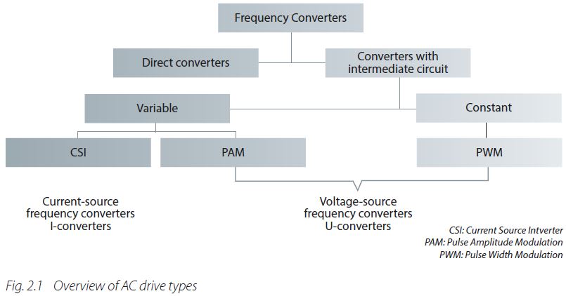
As stated in the introduction, the main function of an AC drive is to generate a variable supply (for example, 0 to 400 V / 0 to 50 Hz) from a supply with “fixed” parameters (for example, 400 V and 50 Hz). There are two approaches to performing the conversion, defining two types of drives: Direct converters and AC drives with an intermediate circuit.
3.1 Direct Converters
The direct converter performs the conversion with no intermediate storage.
Direct converters are generally only used in high-power applications (megawatt range).This book does not deal with this type of converter in detail, but several features are worth mentioning.
Direct converters are characterized by:
• Reduced frequency control range (approximately 25 to 30 Hz) with 50 Hz mains frequency
• Common use with synchronous motors
• Suitability for applications with stringent dynamic performance requirements
3.2 AC Drives with an Intermediate Circuit
In the vast majority of cases, the AC drive is equipped with an intermediate circuit. Another term for intermediate circuit is “DC-bus” or “DC-link”. Within the category of AC drives with an intermediate circuit, there are two subtypes:
• constant intermediate circuit
• variable intermediate circuit
AC drives with an intermediate circuit can be broken down into four main components as shown in Fig. 3.2 Block diagram of an AC drive with an intermediate circuit.
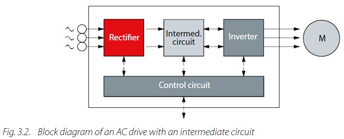
Rectifier
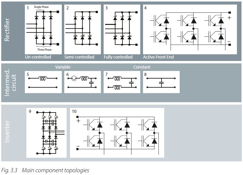
The rectifier is connected to a single-phase or three-phase AC mains supply and generates a pulsating DC voltage. There are four basic types of rectifier, as shown in Fig. 3.3 Main component topologies:
• uncontrolled
• semi-controlled
• fully controlled
• active front-end
Intermediate circuit
The intermediate circuit can function in two different ways, as shown in Fig. 3.3 Main component topologies Intermediate circuit:
• Conversion of the rectifier voltage into a DC voltage
• Stabilization or smoothing of the pulsating DC voltage to make it available to the inverter
Inverter
The inverter converts the constant DC voltage of the rectifier into a variable AC voltage andgenerates the frequency of the motor voltage. See Fig. 3.3 Main component topologies Inverter.
Control circuit
The control circuit transmits signals to – and receives signals from – the rectifier, the intermediate circuit and the inverter. The design of the individual AC drive determines specifically which parts are controlled.
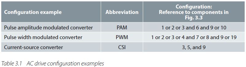
Configuration of the AC drive involves selection between different main components. See tableConfiguration of the AC drive involves selection between different main components. See table 3.1 AC drive configuration examples.
 What all AC drives have in common is that the control circuit uses signals to switch the inverter semiconductors on and off. This switching pattern is based on a variety of principles. AC drives can further be broken down into types according to the switching pattern that controls the supply voltage to the motor.
3.3 Rectifier
Depending on the power involved, the power supply takes the form of a three- phase AC voltage or a single-phase AC voltage with a fixed frequency.
For example:
Three-phase AC voltage: 3 x 400 V/50 Hz
Single-phase AC voltage: 1 x 230 V/50 Hz
The rectifier of an AC drive consists of diodes or thyristors, a combination of both, or bipolar transistors (IGBTs).
Fig.3.3 Main component topologies shows the four different rectification approaches that are available today. In low-power applications (up to 30 kW, depending on the manufacturer), uncontrolled B6 bridge rectifiers are generally used. Half-controlled rectifiers are used in the power range 30 kW and above.
The rectifier circuits described above allow energy to flow in one direction, from the supply to the intermediate circuit.
3.3.1 Uncontrolled rectifiers
Uncontrolled rectifiers consist of diodes as shown in Fig. 3.4 How diodes work.
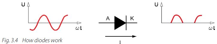
A diode allows current to flow in one direction only: from the anode (A) to the cathode (K). The current is blocked if it attempts to flow from the cathode to the anode. It is not possible to control the current strength, as is the case with some other semiconductors. An AC voltage across a diode is converted into a pulsating DC voltage. If a three-phase AC voltage is supplied to an uncontrolled three-phase rectifier, the DC voltage will pulsate continuously.
Fig. 3.5 Uncontrolled rectifier (B6-diode bridge) shows an uncontrolled three-phase rectifier consisting of six diodes, also commonly referred to as a 6-pulse rectifier. The diodes can be divided in two groups. One group consists of diodes D1, D3 and D5. The other group consists of diodes D2, D4 and D6. Each diode conducts for one third of the period T (120°).
In both groups, the diodes conduct in sequence. Periods during which both groups conduct are offset in relation to each other by one sixth of the period T (60°).
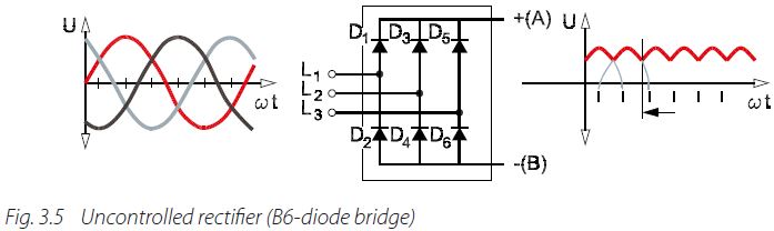
Diode group D1,3,5 conducts the positive voltage. When the voltage of phase L1 reaches the positive peak value, terminal (A) takes on the value of phase L1. Reverse voltages of the magnitude UL1-2 and UL1-3 are present across the other two diodes.
The same principle applies to diode group D4,6,2. Here terminal (B) takes on the negative phase voltage. If, at a given time, L3 reaches the negative threshold value, diode D6 conducts.
The other two diodes are subject to reverse voltages of the magnitude UL3-1 and UL3-2.
The DC output voltage of the uncontrolled rectifier is constant and represents the difference between the voltages of the two diode groups. The average value of the pulsating DC voltage is approximately 1.31 to 1.41 times the mains voltage with a three-phase supply or approximately 0.9 to 1.2 times the AC voltage in the case of a single-phase supply.
The current consumption of the diodes is not sinusoidal. Consequently, uncontrolled rectifiers generate mains interference. To counteract this, AC drives with B12 rectifiers are increasingly used. B12 rectifiers comprise 12 diodes, organized in groups of 6. They are commonly referred to as 12-pulse rectifiers (see chapter 8.3.1).
3.3.2 Semi-controlled Rectifiers
In the case of semi-controlled rectifiers, a thyristor group takes the place of one of the diodegroups (for example, D4,6,2 as shown in Fig. 3.5 – Uncontrolled rectifier (B6-diode bridge).The thyristors are also referred to as silicon-controlled rectifiers (SCR). SCRs are found in manyapplications in electronics, and in particular for power control.
By controlling the firing times of the thyristors, it is possible to limit the inrush current of the units and achieve soft-charging of the capacitors in the intermediate circuit.
The output voltage of these rectifiers is identical to that produced by uncontrolled rectifiers. Typically, semi-controlled rectifiers are found in AC drives of power size 37 kW and greater.

Referring to Fig. 3.6 How thyristors work, when α is between 0° and 90°, the thyristor circuit is used as a rectifier. When the α value is between 90° and 300° the thyristor circuit is used as an inverter.
3.3.3 Fully-controlled Rectifiers
Fully-controlled rectifiers involve the use of thyristors. As with a diode, a thyristor permits the current to flow from the anode (A) to the cathode (K) only. However, the difference is that the thyristor has a third terminal known as the gate (G). When the gate is triggered by a signal, the thyristor will conduct. Once current starts flowing through the thyristor, it will continue conducting until the current drops to zero. The current cannot be interrupted by sending a signal to the gate.
Thyristors are used in rectifiers. The signal sent to the gate is known as the α control signal of the thyristor. α is a time delay, which is specified in degrees. The degree value indicates the delay between the voltage zero crossing and the time when the thyristor is triggered.
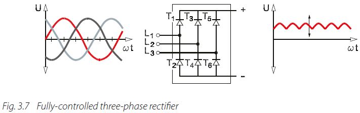
Fully-controlled three-phase rectifiers can be broken down into two groups of thyristors: T1, T3 and T5, on the one hand, and T4, T6 and T2 on the other. With fully controlled rectifiers, α is calculated from the moment when the corresponding diode in an uncontrolled rectifier would normally begin to conduct, that is, 30° after the voltage zero crossing. In all other respects, controlled rectifiers behave like uncontrolled rectifiers.
The amplitude of the rectified voltage can be varied by controlling α. Fully-controlled rectifiers supply a DC voltage with an average value U, where
U = 1.35 x Umains × cos α.
Compared to uncontrolled rectifiers, fully-controlled rectifiers result in major losses and disturbances in the supply network, because they draw a high reactive current when the thyristors conduct for short periods. However, the advantage of fully-controlled rectifiers is that they enable regenerative braking power in the intermediate circuit to be fed back to the supply network.
3.3.4 Active Front-End / Active Infeed
For certain AC drive applications, the motor sometimes works as a generator. In these cases, the energy balance can be improved by returning energy to the supply grid.
Such AC drives require a controlled (active) rectifier, which allows energy to flow backwards. Therefore, these devices are called Active Front-End (AFE) or Active Infeed Converters (AIC). Precondition for feeding back energy to the supply grid is that the voltage level in the intermediate circuit is higher than the grid voltage. This higher voltage must be maintained in all operating conditions. Various strategies are available to reduce the losses during standby and motor operation, but none can completely eliminate losses. Further additional filtering is required in generative mode as the generated voltage does not fit the sine-wave shape of the supply grid. One way to utilize the regenerated energy is by coupling the intermediate circuit of the drive (see chapter 5.9.1).
Another reason for using an AFE is, that they are also efficient at limiting harmonics(see chapter 8).
3.4 Intermediate Circuit
Depending on the design, the functions performed by the intermediate circuit include:
• Acting as an energy buffer so that the motor can draw energy from/return energy to the grid via the inverter and as a means of accommodating intermittent load surges
• Decoupling the rectifier from the inverter
• Reducing mains interference
The intermediate circuit is based on one of four different basic circuits, shown in Fig. 3.3 Main component topologies. The type of intermediate circuit used is determined by the nature of the rectifier and inverter with which it is to be combined.
The basic differences between the various types of intermediate circuit are explained in thefollowing sections.
3.4.1 Variable Intermediate Circuit
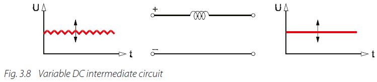
This type of intermediate circuit consists of a very large inductor, also known as a “choke” or “reactor” and is combined with a fully controlled rectifier as shown in Fig. 3.3 Main component topologies part 5, and Fig. 3.8 Variable DC intermediate circuit.
The inductor converts the pulsating DC voltage from the fully controlled rectifier into a constant DC voltage. The load determines the size of the motor voltage. The advantage of this kind of intermediate circuit is that braking energy from the motor can be fed back into the supply network without the need for additional components. The inductor is used in current-source AC drives (I-converters).
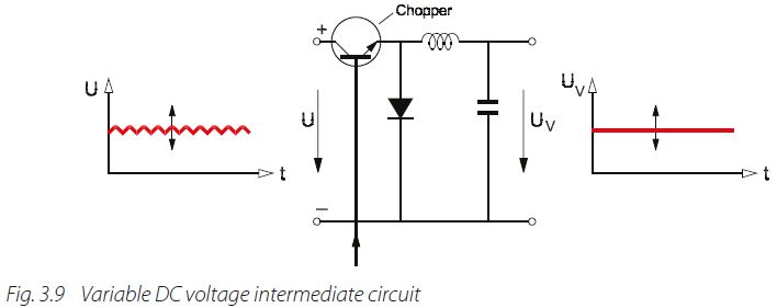
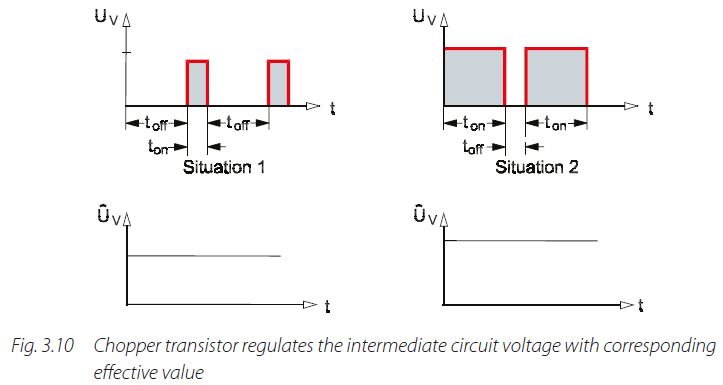
Finally, a chopper can be inserted in front of a filter, as shown in Fig. 3.9 Variable DC voltage intermediate circuit. The chopper contains a transistor which acts as a switch for turning the rectified voltage on and off. The control circuit regulates the chopper by comparing the variable voltage after the filter (UV) with the input signal. If there is a difference between these values, then the ratio of the time ton (when the transistor is conducting) to the time t-off (when the transistor is blocking) is adjusted.
This makes it possible to vary the effective value of the DC voltage depending on how long the transistor conducts. This can be expressed as:
UV = U × t-off
t-on + t-off
When the chopper transistor interrupts the current, the filter inductor (or “choke”) attempts to produce an infinitely high voltage across the transistor. To prevent this from happening, the chopper is protected by a freewheeling diode, as shown in Fig. 3.9 Variable DC voltage intermediate circuit.
 The filter in the intermediate circuit smooths the square-wave voltage after the chopper, while keeping the voltage constant at a given frequency. The frequency associated with the voltage is generated in the inverter.
3.4.2 Constant Intermediate Circuit
The intermediate circuit can consist of a filter comprising a capacitor and/or an inductor (choke). Typically, electrolytic capacitors are used due to their high energy density. Although capacitors have a limited service life, they offer the following benefits:
• Smoothing of pulsating DC voltage (UZ1)
• Availability as an energy reserve for supply voltage drops
• Availability for energy storage for load surges and generative operation of the motor
DC inductors offer the following advantages:
• Smoothing of current ripple, which in turn increases the service life of the intermediate circuit components, especially the capacitors
• Reduction of mains interference (harmonics) and the option of smaller supply conductor cross sections. This function can also be implemented by means of line inductors upstream of the AC drive
When planning an installation, it is important to note that the inductors are heavy and can get hot. Hot spots can arise.
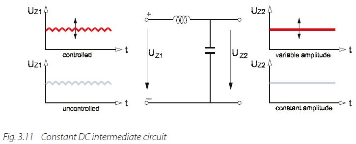
This form of intermediate circuit can be combined with various types of rectifier. In the case of fully controlled rectifiers, the voltage is kept constant at a given frequency. Thus, the voltage that is supplied to the inverter is a pure DC voltage (UZ2) with variable amplitude.
With semi-controlled or uncontrolled rectifiers, the voltage at the inverter input is a DC voltage with constant amplitude (approximately √2 times the mains voltage). The anticipated voltage and frequency are both generated in the inverter.
3.4.3 Capacitorless Intermediate Circuit
In the last few years manufacturers have devised intermediate circuits without capacitors and inductors (chokes). This has been generally termed “capacitorless” or “slim” intermediate circuit. The control circuit controls the rectification of the supply voltage in a way that lower inrush currents can be achieved and so that mains interference can be limited to values of less than 40% (fifth harmonic). This results in the following characteristics:
• Lower building cost
• No charging circuit required
• More compact and lower weight construction
• Susceptibility to supply system voltage dips. That is, the AC drive is more likely to trip in the event of voltage dips, due to transients in the supply system
• Mains interference can occur in the high frequency spectrum
• The high ripple associated with the intermediate circuit reduces the output voltage by approximately 10% and results in higher motor power consumption
• The restart time for operation may be longer, due to three processes occurring:
• Re-initialization of the AC drive
• Magnetization of the motor
• Ramping up to the required reference for the application
3.4.4 Common DC Bus
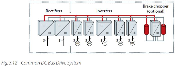
Intermediate circuits of AC drives can also be connected, and the DC voltage shared between several inverters. In applications with several parallel motors, instead of installing separate AC drives for each motor, it is possible to use a so-called common DC bus drive.
A common DC bus drive system consists of one or more front end units (rectifiers) that convert the mains AC voltage into DC voltage and current, providing power to the common DC bus. The common DC bus transfers the power to the inverter drives, and depending on the type of the front end, in some cases back to the mains network. A common DC bus drive system may also include a brake chopper unit, as a cost-effective solution for dissipating the braking energy in cases where regeneration of the power to the network is not feasible.
The common DC bus configuration can bring significant energy savings when the braking energy is used. This is the case when there is more than one drive connected to the DC bus, and at least one of them is braking. The braking power is directly fed to the other drives via the common DC bus.
3.5 Inverter
The inverter is the last of the main elements making up the AC drive. The inverter processes represent the final stage in terms of generating the output voltage and frequency. When the motor is connected directly to the mains, the ideal operating conditions apply at the rated operating point.
The AC drive guarantees good operating conditions throughout the whole speed range by adapting the output voltage to the load conditions. It is thus possible to maintain the magnetization of the motor at the optimal value.
From the intermediate circuit, the inverter obtains one of the following:
• Variable direct current
• Variable DC voltage
• Constant DC voltage
In each case, the inverter must ensure that the supply to the motor is an AC voltage. In other words, the frequency of the motor voltage must be generated in the inverter. The inverter control method depends on whether it receives a variable or a constant value. With a variable current or voltage, the inverter only needs to generate the corresponding frequency. With a constant voltage, the inverter generates both the frequency and amplitude of the voltage.
Even though inverters work in different ways, the basic design is always the same. The main components are controlled semiconductors, arranged in pairs in three branches, as shown in Fig. 3.3 Main component topologies.
Transistors are increasingly taking the place of thyristors in the inverter stage of AC drives for several good reasons. Firstly, transistors are now available for large currents, high voltages and high switching frequencies. Furthermore, unlike thyristors and diodes, transistors are not affected by the current zero crossing. Transistors can enter the conducting or blocking state at any time simply by changing the polarity of the voltage applied to the control terminals. The advances made in the field of semiconductor technology over recent years have increased the switching frequency of transistors significantly. The upper switching limit is now several hundred kHz.
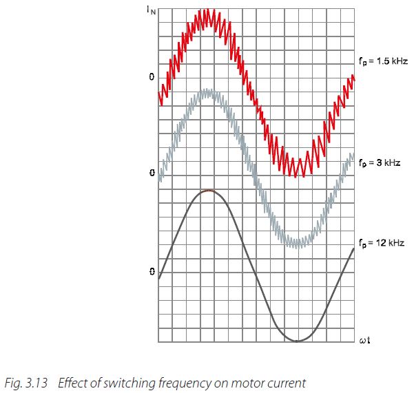
Thus, magnetic interference caused by pulse magnetization within the motor can be avoided. Another advantage of the high switching frequency is the fact that it allows variable modulation of the AC drive output voltage. This means that a sinusoidal motor current can be achieved, as shown in Fig. 3.13 Effect of switching frequency on motor current. The control circuit of the AC drive merely has to switch the inverter transistors on and off in accordance with a suitable pattern.

The choice of the inverter switching frequency is a trade-off between losses in the motor (sine shape of motor current) and losses in the inverter. As the switching frequency increases, so do the losses in the inverter, in line with the number of semiconductor circuits.
High-frequency transistors can be divided into three main types:
• Bipolar (LTR)
• Unipolar (MOSFET)
• Insulated Gate Bipolar (IGBT)
Table 3.2 Comparison of power transistor characteristics shows the key differences betweenMOSFET, IGBT and LTR transistors.
IGBT transistors are a good choice for AC drives in terms of the power range, the high level of conductivity, the high switching frequency and ease of control. They combine the features of MOSFET transistors with the output properties of bipolar transistors. The actual switching components and inverter control are normally combined to create a single module called an “intelligent power module” (IPM).
A freewheeling diode is connected in parallel with each transistor, because high induced voltages can occur across the inductive output load. The diodes force the motor currents to continue flowing in their direction and protect the switching components against imposed voltages. The reactive power required by the motor is also handled by the freewheeling diodes.