Understand the Fundamentals of Coaxial Adapters to Make Better Use of These Very Useful Components
January 4, 2021
By Art Pini, Editor, DigiKey North America division
Users of electronic instrumentation equipment that involves the transmission or reception of high-frequency electrical signals are familiar with coaxial connections as they are used prolifically. So much so that such connection types can be taken somewhat for granted—until it comes time to connect multiple instruments together or extend coaxial cables. At this point, designers or other equipment users may turn to adapters; but before doing so, they need to fully understand the implications and characteristics of each type of adapter they may use.
There are a wide variety of adapters for a reason. “Tees” connect a single signal source to multiple instruments, while “barrels” extend coaxial cable connections. Then there are DC blocks, bias tees, impedance pads, surge protectors, and terminations—all of which are commonly used, but sometimes not fully understood. The correct use of these adapters requires some basic knowledge of transmission lines and care during selection.
This article provides a brief overview of transmission lines. It then introduces various types of coaxial adapters, describes how they operate, and shows how best to apply them. Real-world examples from Amphenol RF, Amphenol’s Times Microwave Systems, and Crystek Corporation are used.
What are transmission lines?
Transmission lines, in the form of coaxial cables, flat line, microstrip, or others, connect a signal source to a load. Transmission lines have a characteristic impedance determined by the physical dimensions of the conductors, their spacing, and the dielectric material used to isolate the conductors. Coaxial cables most commonly have a characteristic impedance of 50 Ohms (W) for general RF work, or 75 W for video applications.
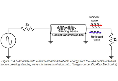
To assure the maximum efficiency in transferring power from the source to the load, the impedance of the source, the characteristic impedance of the transmission line, and the load impedance should be matched. If the impedances differ then some energy is reflected from the mismatched junction. For example, if the load impedance differs from the source and transmission line impedance, then energy is reflected from the load back toward the source (Figure 1).
The incident and reflected waves additively combine along the transmission path forming standing waves where the amplitude varies periodically over the physical length of the path. Standing waves cause measurement errors and can result in damage to components. Impedance matching of the source, transmission line and load prevents the creation of standing waves, and so helps assure the most efficient transmission of power from the source to the load.
Due to the impedance matching requirements, it’s important to use the right adapter; but as the designer will soon discover, adapters are many and varied, and often come with features that go beyond forming a basic connection.
Tee adapters
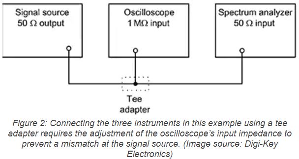
Consider a basic instrument system consisting of a single source, oscilloscope, and spectrum analyzer (Figure 2).
The signal source has an output impedance of 50 Ω and is intended to operate into a 50 Ω load. If a tee adapter is used to connect the oscilloscope and the spectrum analyzer with both set to 50 Ω input terminations, the signal source will see a 25 Ω load, reducing its output and set up standing waves on the cables. The secret here is to set the instrument in the middle of the coaxial run to a high-impedance input termination, and the instrument at the far side of the coaxial run to its 50 Ω input termination, as shown. The signal source will see this as a 50 Ω load, and all will be well.
The Amphenol RF 112461 is a BNC tee with a single BNC plug, two BNC jacks, and a bandwidth of 4 gigahertz (GHz). It could be used in the configuration shown in our example for instruments with bandwidths below 4 GHz.
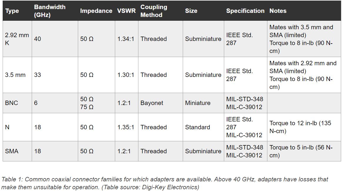
The type of tee to select depends on the connectors used on the instruments and will be based on the bandwidths of the respective instruments. In general, coaxial adapters like tees are not available for bandwidths in excess of 40 GHz since signal losses become problematic in adapters at these frequencies. A list of the common instrument coaxial connectors for which adapters are generally available is shown, along with their salient attributes (Table 1).
Connector family adapters
Having multiple connector types gives rise to the need to be able to convert from one type of connector to another. Consider having to fit an SMA cable from the input BNC connector on an oscilloscope or spectrum analyzer. For this situation, the Amphenol RF 242103 provides a BNC plug to connect to the instrument and an SMA jack to receive the SMA cable.
Equipment users should keep in mind that whenever an adapter is used, the bandwidth of the interconnect is reduced to the lower bandwidth of the two connector families. In the case of the BNC to SMA adapter, the bandwidth is 4 GHz, inherited from the BNC.
There are also adapters that offer impedance changes from 50 to 75 Ω and vice versa.
Barrel and bulkhead adapters
Extending cables or bringing a cable through a panel requires the use of straight-through (barrel) or bulkhead adapters. These are available for the families of connectors shown in Table 1. An example is the Amphenol RF 132170 bulkhead adapter, which has two SMA jacks to which cables using SMA plugs can connect on either side of a bulkhead or panel.
Barrel connectors can be configured as jack to jack, or as plug to plug, and less commonly as plug to jack.
Terminations
Connecting multiple high-impedance input instruments in series from a 50 Ω source requires a 50 Ω termination (Figure 6). The Amphenol RF 202120 50 Ω terminator is an example of a coaxial termination configured as a BNC jack.

The BNC jack accepts coaxial cable directly. There are also terminations in the form of BNC plugs that mate with a BNC jack. These are useful when terminating an instrument directly on its front panel. While most oscilloscopes offer both high impedance and 50 Ω inputs, there is a voltage limit on the 50 Ω scope inputs, usually 5 volts. Oscilloscopes also have a 0.5 watt power limit on their 50 Ω inputs. The 202120 is rated at 1 watt and can handle over 7 volts.
Terminations are also available for other impedances. For instance, 75 Ω terminators are commonly used in television and video applications. Zero Ω or short circuit terminations are used when calibrating network analyzers.
DC blocks and bias tees
The DC block is a coaxial adapter that blocks direct current signals and allows the passage of RF signals. It is used to protect sensitive RF components from DC, which is blocked by a capacitor. There are three types of DC block:
- – An inner DC block uses a single capacitor in series with the inner or center conductor of the coaxial cable
- – An outer DC block has a capacitor in series with the shield conductor of the coaxial cable
- – An inner/outer DC block has capacitors in series with both the inner and outer conductor
All types of DC blocks are designated for specific characteristic impedances, usually 50 or 75 Ω. The Crystek Corporation CBLK-300-3 is a 50 Ω, inner conductor DC block that passes signals with frequencies from 300 kilohertz (kHz) to 3 GHz, while blocking DC levels of up to 16 volts with low insertion and return losses over its operating frequency range.
Bias tee
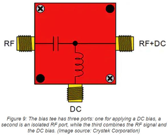
The bias tee is related to the DC block. It is a three-port adapter where DC power is applied to one port. A second port combines the DC bias with the incident RF signal from an isolated RF port (Figure 9).
Bias tees are used to supply power to remote electronics, like a low noise amplifier (LNA) mounted on an antenna with DC power, while providing a DC-free port to connect an RF receiver. DC bias is applied through a series inductor, which blocks RF from being applied to the DC source. Like a DC block, the RF-only port is isolated from the DC input by a series capacitor. The combined port passes both the RF and DC components.
The Crystek Corporation BTEE-01-50-6000 is a bias tee with an RF bandwidth of 50 megahertz (MHz) to 6 GHz using SMA jacks. The RF port accepts an RF signal with a maximum power level of 2 watts. The DC port has a maximum DC input of 16 volts. The insertion loss of the bias tee is typically 0.5 decibels (dB) at 2 GHz. In operation the RF+DC port is connected to the LNA and antenna. The DC power source is connected to the DC port and the receiver is connected to the RF port.
In-line filters
Another useful coaxial adapter is the in-line filter. Low-pass, high-pass, and bandpass filters are available for BNC or SMA connector types. These are applied to control the spectrum of the signal being transmitted on the cable. For instance, to measure the effective number of bits in an analog-to-digital converter (ADC), a low-pass filter would be inserted between the signal generator and the ADC. The filter will attenuate the generator’s harmonic levels, thereby vastly improving the measurement accuracy. This allows a lower cost signal generator to be used.
A good example of such a device is Crystek’s CLPFL-0100, a 7th order, 100 MHz low-pass filter with a cutoff frequency of 100 MHz.
A 100 MHz input signal will have its second harmonic attenuated by 30 dB and its higher harmonic attenuated by better than 60 dB. If the signal generator in the example above had a harmonic level specification of -66 dB, the filter would reduce it to under -96 dB.
Surge protectors
Surge protectors, sometimes called lightning arrestors, protect sensitive electronics from transient surges, like lightning. This can be done with spark gaps, gas tubes, or diodes that break down electrically to discharge electrical surges to ground before they can damage the protected devices.
The Amphenol Time Microwave Systems LP-GTR-NFF is an N-type connector in-line surge protector that uses a replaceable gas discharge tube. The tube breaks down at DC voltages above ±90 volts/20 A and can handle surges of up to 50 watts. It is inserted in line and has a bandwidth of from DC to 3 GHz with an insertion loss of 0.1 dB up to 1 GHz and 0.2 dB up to 3 GHz.
Surge protectors are generally mounted on L-brackets that are tied electrically and mechanically to a low-impedance ground using large, low-inductance conductors. It’s important to note that the quality of the ground connection affects the performance of the surge protector.
In-line attenuators
Attenuators reduce the power level of a signal without distorting the signal waveform. Coaxial in-line versions offer a fixed attenuation and are available in a large number of connector types with a variety of plug and jack configurations.
The Crystek Corporation CATTEN-03R0-BNC is a 3 dB, 50 Ω, BNC attenuator with a bandwidth of 0 to 1 GHz and a power rating of 2 watts. It is one of thirteen attenuator models available in its product line with attenuations of from 1 to 20 dB.
In-line attenuators obviously are used to step down the power level of a signal, but less obviously, they are also used to provide isolation between impedances in serially connected devices, as well as to reduce impedance mismatches and unwanted reflections.
Consider inserting a matched 3 dB attenuator in front of a mismatched load impedance. The attenuator input signal is reduced by 3 dB by the attenuator as it propagates to the mismatched load. Assuming the mismatch is an open circuit, then the entire signal is reflected at the load and bounced back through the attenuator where it suffers another 3 dB loss at the attenuator input. The return loss at the attenuator input is improved by 6 dB. The mismatch observed at the input of the attenuator is improved by an amount equal to twice the value of the attenuator—in this case the total reduction is 6 dB.
This technique has a disadvantage in that the amplitude of the through signal is reduced by 3 dB, which must be compensated for elsewhere in the network. The Crystek CATTEN-03R0-BNC would work well in this application.
Conclusion
When connecting instruments or other devices with coaxial adapters, designers and other equipment users need to be aware of transmission line basics. Once those are understood, users can better take advantage of these very useful components with their broad range of utility, including changing connector types and characteristic impedances, signal branching, filtering, surge protection, signal attenuation, and DC control and isolation.