Parker Hannifin: Safe Stopping Distance with Safety Exhaust Valves
April 30, 2019
By Linda Caron, Parker Hannafin
Safe Distance in Machine Design When machine safeguarding is used one of the most relevant (and least discussed) effective measures is safe placement of the equipment in relation to the hazard. This is especially true when trying to comply with the requirements to eliminate trapped energy under ISO 13849-1 where exhaust time and volume of compressed air in the machine play a role in creating a safe condition. Considerations must include those questions posed in a risk assessment such as severity of injury, frequency of exposure and so we begin to look at all aspects of the machine design.

International Standard ISO 13855 “Safety of Machinery – Positioning of safeguards with respect to
the approach speeds of parts of the human body.”; defines these standards. Most commonly considered is how quickly can we bring the machine to a safe state? And, how far do we place the safety equipment to the hazard? We must not forget to include the switching time for machine safety devices and exhaust rates in faulted conditions. Exhaust flow is not mentioned but ultimately is a critical part of bringing a pneumatic machine to a safe state.
The time taken to ensure the safe condition of the machine is met is a combination of products, switching time and flow rates. These calculations cannot be done until you have identified which safety products you will utilize because they all have different flow rates and exhaust times. Faulted flow rates are flow rates in the worst-case scenario and are important considerations in calculating safe distances. You really want to know your exhaust time in choosing components because ultimately these times will impact where you place your machine guards.
Now, Let’s Consider T (time interval)
 Standards do not exist to explain the correlation of exhausting and spacing leaving the engineering community to use a common- sense approach on how to integrate safety exhaust valves.
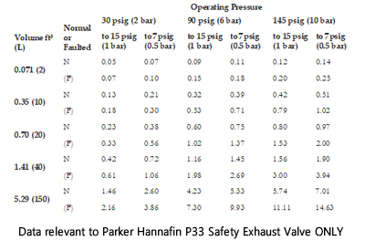
The closest the standards come is to say the “overall system stopping time”. For safety this time interval would ideally include time to exhaust however, this is not always practical. Most suppliers of pneumatic safety exhaust valves will provide their data for varying machine volumes (as follows).
Note – a machine with 150L of trapped air at 6 bar needs 7.30 seconds to exhaust in faulted condition so it may not be practical to assume full exhaust of a large machine but rather how to responsibly ensure safety and utilize this data to make the best decision for your application.
Size for Both Switching Time and Exhaust Time Where Possible
Of critical consideration before selecting equipment is its switching time and exhaust time. I would say it is good engineering practice to include the switching time and the exhaust time of such a component in the safe distance calculations when possible. Ideally, hazardous locations would be designed to utilize a small area of compressed air for rapid depressurization but this isn’t always possible for the existing situation in the case of retrofitting a machine.
Including exhaust time is not always possible given the large size of some machines which may take several seconds to exhaust. Here, sound judgement and good engineering principles come into play. Once open to exhaust, the safety valve will begin to reduce the pressure build up in the machine rapidly bringing the machine finally to a safe state. If you are unable to space by exhaust time practically, there are some additional things you can do to enhance the safety such as safe stopping devices like rod locks or clamps.
Concluding Safe Distance with Exhausting Products
Safety exhaust valves serve three primary functions. The first is rapid exhaust of compressed air. The second function is to prevent a restart if a fault is detected. The third in the case of redundant designs is to ensure both channels are operational or to fail safe / exhausted (even if no power is available).
Consider Faulted Exhaust Time
Chose the safety exhaust valve with the quickest faulted exhaust time to depressurize the machine as quickly as possible. If your machine has a volume of 5.30 ft3 (150 L) operating at 90 psig or 6 bar. The Parker P33 will exhaust in faulted condition (worst case) in 7.30 seconds. Use the manufacturer’s faulted exhaust time data to understand your situation fully.
Utilize secondary means
When the machine takes time to exhaust and an unsafe condition is still present utilize secondary means of stopping, blocking or holding a load in place such as clamping and rod locks.
Double up
If your pneumatic air supply offers enough pressure to meet the minimum operation pressure requirements of the safety exhaust valve, consider using two safety exhaust valves (as shown to the right). This is especially useful on large machines. Parker safety exhaust valves need a minimum 30 psi at P1.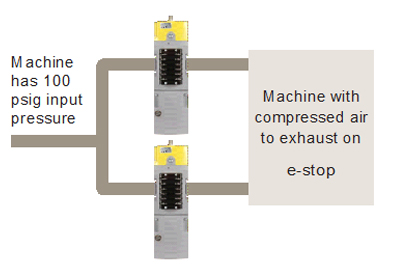
Each safety valve requires a minimum input pressure of 30 psig
Follow the Standards which provide greater detail to the height of machine guards and the basic safe distances required for parts of the body. Further, stop-time measurement devices are to be used to measure the time it takes a machine to stop after a signal is given. Only then can the safeguarding device’s location
(ie light curtain) be established in relation to the hazard with the safety distance in consideration. Calculating where to put safety input devices like gates or light curtain is a critical step in machine design. Determine machine guard spacing prior to building and testing the machine. It’s also important to check the stop-
time device as part of your plant maintenance routine to ensure the machines stopping ability has not been compromised by wear or tampering.
Visit Parker Hannafin