Servo and Other PWM Motors in Semiconductor Manufacturing
October 24, 2024

By Vladimir Kraz/OnFILTER
Semiconductor manufacturing is largely fully automated. The only time any device – from the wafers to the packaged ICs – is handled manually is when these components are already “dead.” The same is largely true for automated PCB assembly (PCBA) with some exceptions for manually inserted components, rework, and low-volume testing. No automation is possible without the ability to move parts in the process, and this is done by pulse-width modulation (PWM) motors – servo and stepper motors, and variable frequency drives (VFD).
These motors are ubiquitous in any automated equipment. In this article we will discuss two distinct problems caused by sharp drive pulses—bearing damage with its effects and flooding the equipment with EMI.
Although there are substantial differences in the operation and construction of these three types of motors, one thing is common – they all operate on pulses. Pulse timing and width control the direction of rotation, its speed, and the rotor’s position in many of them.
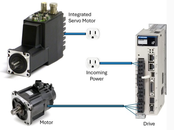
Typical configurations of PWM motors are shown in Figure 1. Most frequent consists of motor itself and drive (also called “amplifiers” or “controllers” – the control unit that tells the motor what to do). Connection shown is only for power and drive signals for clarity. A more recent entry is integrated motors that combine motor with the drive in one unit. Their differences as far as EMI is concerned are outlined further in this article.
PWM motors have a lot going for them: precision, flexibility, ease of control, efficiency, compact size. They are irreplaceable by regular AC or DC motors. But these motors have their dark side – sharp edges of driving pulses (also called “carrier”). The frequency or the duty cycle of these pulses isn’t as critical as the sharpness of their edges — both rise and fall.
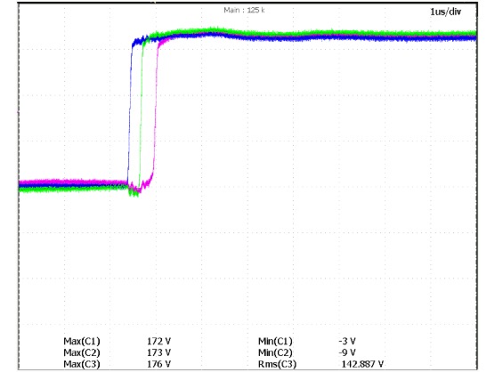
Figure 2 shows the front edges of the drive pulses of a servo motor. The servo and VFD motors are three-phase, hence three pulses shown; (stepper motors can be a bit more complicated). In a typical drive the rise/fall edge of such pulse is ~50 nanoseconds narrow. Why that fast?
Consider yourself a designer of a motor’s drive — a control unit. One of your design goals is to reduce heat dissipation, lowering the cost, and reducing the physical size of the controller. The majority of power consumption in the amplifier is in its output stage—usually, a push-pull arrangement of power transistors applying pulsed voltage to the motor.
Most heat dissipation in the drive occurs when these transistors are transitioning from either being closed or open — at that time there is a gradual voltage change across the transistors and, consequently, high power dissipation in the transistors resulting in heat and power losses. Transistors need to be “beefier” and be mounted on large heat sinks. As a designer, you see these transitions as a waste in more ways than one. You strive to improve the situation by shortening these transitions by selecting faster output transistors and optimizing the drive circuit.
This results in an efficient and a reasonably small output stage, and the entire drive. The rise and fall pulses are as short as you can make them—just a few nanoseconds; good job! Your mission is accomplished.
Now let’s change the hat to the one of an engineer or a technician who deals with this controller and a motor in actual use. The motor seems to work well, moving robotic arms nicely. That is, until you realize that something is happening with the electronics in your equipment: random errors, software issues, data corruption, and sometimes a total lock-up. After blaming Microsoft or whatever software package the tool is using, something on the back of your mind begins to tell you that perhaps, just maybe, the software isn’t the issue; something else is. What could it be? Not the motor, for sure?
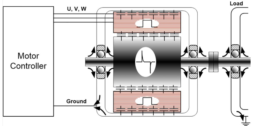
Now let’s take an analytical look at what is happening with the motor. Figure 3 provides an illustration of how the sharp pulse edges wreak havoc on the operation of the host equipment. Inside the motor, the rotor (rotating part) is physically very close to the stator (the stationary part) – this proximity is essential for efficient magnetic coupling. It is also quite efficient in being a parasitic capacitor between them. Capacitors’ impedance drops with frequency. Slow (in machine time) drive pulses—just a few kHz—are pretty much stopped by this capacitance.
However, for the pulse edges this capacitance is just like a wire—it is large metal surfaces in the immediate proximity. The sharper the pulses the easier they get from the stator to the rotor. The rotor is mounted on ball bearings which are grounded. Now there is high-frequency voltage on the rotor, on ground, on whatever equipment the motor’s shaft is connected to, and consequent ground current that mirrors the pulse edges. Your equipment is, figuratively speaking, now full of EMI.
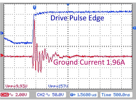
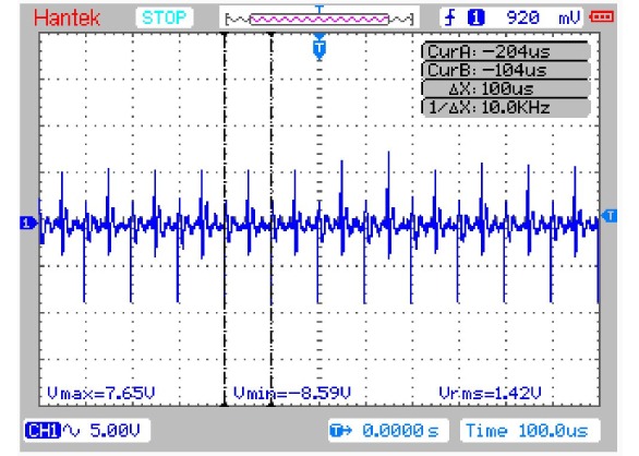
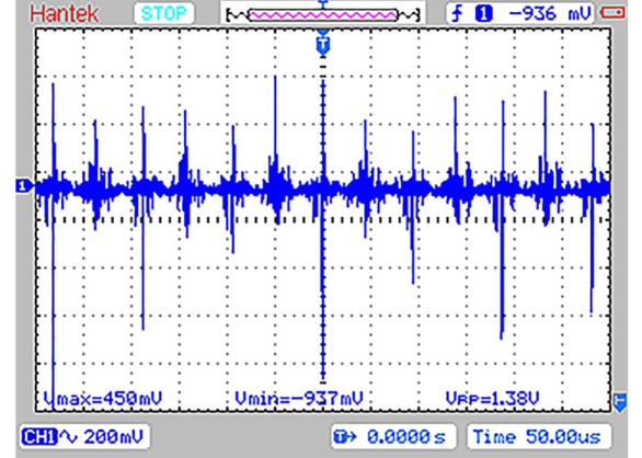
This ground current isn’t small. Figure 4 shows ground current between the motor’s ground and the tool’s ground measured with Tektronix’ CT1 probe with 5mV/mA sensitivity— a 1.96A current as shown in Figure 4. Figure 5 shows a different view of it — as seen, the timing of the current spikes corresponds to 20 kHz — twice the repetition rate of a servo motor’s drive pulses, accounting for both rise and fall times for each pulse.
Wait a minute, one may say. “Isn’t the motor grounded well so that all possible voltages would simply sink to the “absolute” ground, leaving nothing to even notice?” This would be close to truth for the DC or for the AC mains’ frequencies. At high frequencies it is all different.
Two disconnected but placed close enough metal surfaces form a capacitor which is a conductor; a simple wire is an inductor presenting high impedance for such currents. Add to that all the parasitic resonances causing ringing, and you have a rather complex signal waveform on ground as seen in Figure 4.
Figure 5 shows a different view of the same ground current through the servo motor — now you can see pulse repetition rate of 20 kHz—it is twice the pulse rate because the spikes are caused by both rise and fall edges of the drive pulses.
In a typical robotic application in semiconductor manufacturing — IC handler— there are three robotic arms, each with three servo motors, all connected to their drives by cables running in a long flex conduit tightly packed with ground and other wires — a perfect opportunity for sharp drive edges to induce corresponding voltage and currents anywhere they can. Importantly, the robotic arm’s ground is now infected with EMI and has different voltage than the chassis. If this tool weren’t handling sensitive ICs this wouldn’t matter that much.
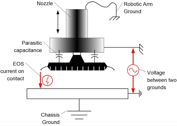
But now the IC is “between a rock and a hard place” – the vacuum pick on the IC handler is capacitively coupled with the IC’s silicon, and the suspended on the vacuum pick IC now has different high-frequency voltage than the chassis which it will come in contact with as shown in Figure 6.
How big is that voltage and how strong is the resulting current? That varies—from milliamps to several amperes. In many cases the current doesn’t appear significant—a few tens of milliamps—what harm can it do? One such pulse –not much.
But, in a case of a typical servo motor, these currents occur 20,000 times a second, every second. Think of a chisel where every hit removes a very small amount of material, but constant chiseling causes a lot of damage. Consider how the Colorado River has cut the deepest trench — The Grand Canyon—just give little water some time.
Electrical Overstress (EOS)
EOS is the number one cause of damage to IC components per Intel [Intel Manufacturing Enabling Guide]. Reports from EOS/ESD Association [Industry Council White Paper 4 rev1.2] indicate EOS as a major source of device damage. EMI currents in manufacturing equipment are one of the top causes of EOS in device manufacturing. Anywhere the device in handling (from the wafer level to placing it on the PCB) has metal-to-metal contact, EOS exposure occurs.
Research (Reliability of CMOS IC Under Square Wave Pulsed EOS, F. Zhu et.al. CEM2014 Conference Paper), indicates that unpowered devices are more susceptible to EOS-caused damage than powered ones — semiconductor manufacturing and PCBA largely deals with unpowered devices, and pulsed exposure models correlate. In short, EOS is a significant concern for semiconductor manufacturing [S. Voldman Electrical Overstress (EOS): Devices, Circuits and Systems, Wiley and Sons, 2014].
One of the specific problems resulting from EOS exposure is device latent damage [Effects of EOS (Electrical Overstress) on components, Jtron, 2020] – when the device is “wounded” but not yet to the degree of failure—the failure will come later in the product’s use, at the most expensive place to fail.
By reducing EMI in the semiconductor manufacturing process, we can substantially reduce EOS exposure to the devices, improving their reliability and production yield.
Electromagnetic Interference (EMI)
Test of devices, as well as of PCBA, often involves low-level and high-speed signals — high levels of EMI in equipment, especially on ground, cause test errors, increasing test time, requiring re-testing, and sometimes ending up in failing good products, or, worse, passing defective ones. Equipment itself may experience what looks like “software” errors due to EMI. Reduction of EMI from PWM motors is the most effective way of improving your test process and equipment up-time.
Bearing Damage
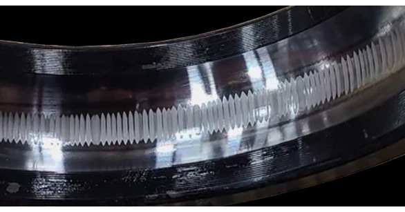
Sharp repeatable current pulses through the bearings cause micro-sparks. Just like a chisel, these micro-sparks take out tiny pieces of metal off the bearings’ rings. This is called EDM — electrical discharge machining, also known as “spark machining.” Normally, EDM is a very useful tool in metal fabrication. EDM causes discharges between two pieces of metal under different voltage separated by a dielectric fluid. Ball bearing is, in essence, pieces of metal (rings and balls) separated by an insulative lubricant.
Sparking causes several specific types of bearing damage: fluting (see Figure 8 [Motor Direct]) and pockmarks/pitting. Sooner or later the bearings stop performing their function and need to be replaced. Bearing replacement is a whole different industry. But before the bearings completely fail, the rotor can start vibrating due to newly uneven surfaces inside the bearing.
This vibration, while maybe not important for many, can be critical for semiconductor manufacturing where precision and very tight tolerances of many processes may suffer. On the wafer level, vibrations can affect the position of the probes that contact pads on the silicon dies, accuracy and position of the wafer saw cuts. On the IC assembly and PCBA levels it may affect positioning of tightly spaced device’s pins on the socket.
In summary, EMI from PWM motors is never a good thing, and proper mitigation improves your productivity, yield, customer relationship, and device reliability.
Dealing With EMI from PWM Motors
EMI issues with the motor are not a new thing, nor a rare one — they were present from the moment PWM motors went into service. Several different methods were used to mitigate this problem, including ceramic bearings, conductive brushes connecting to the motor’s shaft for high-frequency currents to bypass bearing re-directing them straight to ground, reactors—basic common-mode filtering—and ferrite clamps. The two former ones do not reduce EMI pollution in equipment; the two latter ones provide very marginal improvements.
OnFILTER developed an ultimate solution to the motors’ EMI issue: patented motor EMI filters. These filters address the very cause of the problem rather than trying to “soften” the symptoms. More specifically, the OnFILTER’ motor filters alter the drive pulses’ edges as shown in Figure 9.
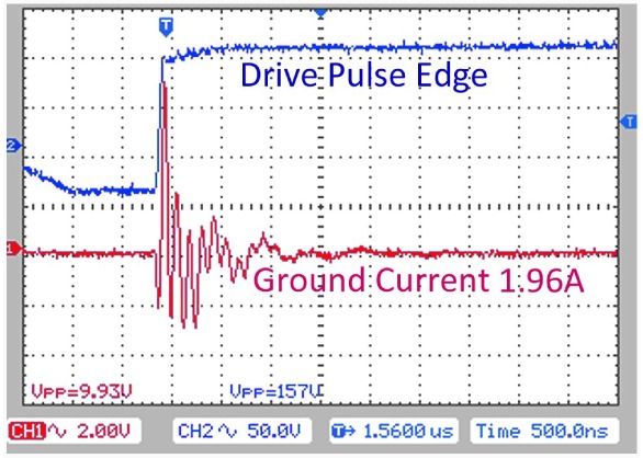
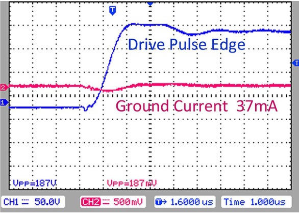
Figure 9: Ground Current Without OnFILTER’s Motor Filter and With the Filter
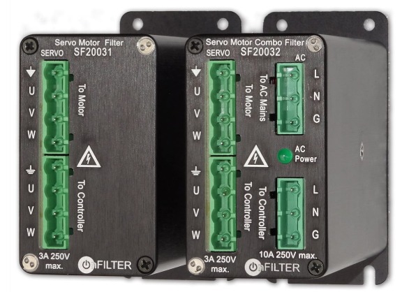
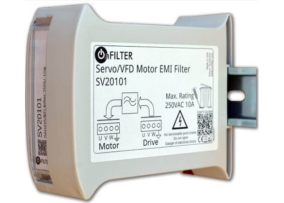
Figure 10: Examples of OnFILTER’s PWM Motor EMI Filters, All Qualify for Inclusion in UL508A Panels
Since most leakage to ground occurs via capacitive coupling between the rotor and the stator, “slowing down” the edges proportionally reduces this leakage without any mechanical parts or fitting, nor any changes in programming.
OnFILTER’ motor filters are truly plug-and-play devices that reduce ground EMI currents and overall EMI pollution of equipment once and for all. Figure 10 shows some of OnFILTER’ PWM
motor filters— all are qualified for inclusion into
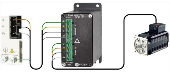
UL508A panels. Connection of such filters is
shown in Figure 11.
Integrated motors that combine controller with the motor in the same enclosure do not have a way of filtering the drive signal. These types of motors would have the strongest high-frequency signal content inside the motor and on ground – consider this when selecting your motion control solution.
What the Future Holds
PWM motors aren’t going away anytime soon. More than that, new types of semiconductors—Gallium Nitrate (GaN) and Silicon Carbide (SiC) offer much shorter transition times than common silicone transistors. Figure 12 shows such an example — 1.2 nanosecond transition vs. typical 50 nanoseconds for silicone. Such 40-fold increase in dV/dt transition proportionally increases current leakage through bearings, increases ground current, and overall EMI levels in tools. Rather than trying to “fix” the problem after the fact, equipment manufacturers and motor users would be better off preventing problems with associated downtime and cost by thinking ahead and implementing EMI management now.
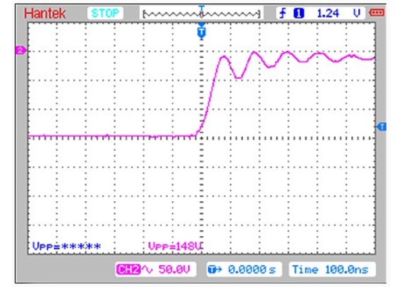
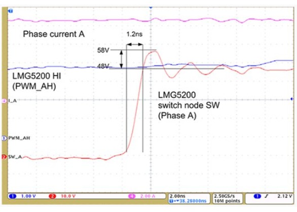
Figure 12: Transition Time of Silicon-Based Drive Output and of GaN-Output of PWM Drive (Texas Instrument)


