Changeover from AS-Interface Gateway K20 to KE5: IIoT-Ready In 3 Steps
February 10, 2023
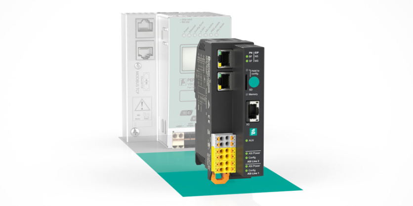
The multiprotocol-capable AS-Interface gateway type KE5 from Pepperl+Fuchs makes your AS-Interface network IIoT-ready. The gateways support PROFINET and EtherNet/IP, and can be easily commissioned using mobile devices. In addition to easy configuration and diagnostics via the extensive web server, the KE5 ASi gateways offer a REST API interface for implementing IIoT solutions. Setup is quick and convenient at the touch of a button.
Are you currently using the K20 gateway with PROFINET interface and want to switch to the multiprotocol KE5 gateway to prepare your AS-Interface network for IIoT applications? Learn in this blog article how to change your gateway in only three steps, from the legacy type K20 to the KE5 ASi gateway VBG-EP1-KE5-D or VBG-EP1-KE5-DMD for two AS-Interface networks according to ASi 3.
Step 1: Switch Connections
Change of Ethernet:
Move the RJ45 PROFINET connections 1 and 2 on the K20 to the ports X1 and X2 on the KE5 gateway VBG-EP1-KE5-D*.

Move the Power Supply on the VBG-EP1-KE5-D:
Move the power supply connections on the K20, ASi PWR- to the connectors marked 03 (+) and 01 (-) on the VBG-EP1-KE5-D.
Note: If you have previously used a K20 gateway with integrated data decoupling, you need to replace the 30 V power supply with the ASi power supply of type VAN-*.

Move the Power Supply on VBG-EP1-KE5-DMD for Two ASi Networks:
Move the power supply connections on the K20 gateway, ASi1+ PWR- and ASi2+ PWR-, to the connectors marked 03 (+), 01 (-) for ASi line 1, and 13 (+), 11 (-) respectively for ASi line 2 on the VBG-EP1-KE5-DMD.
Note: If you have used a K20 gateway with integrated data decoupling so far, you need to replace the 30 V power supply with the two ASi power supplies of type VAN-*.

Move the AS-Interface Network on the VBG-EP1-KE5-D:
Move the ASi connections of the K20, ASi+ ASi-, to connectors marked 04 (+) and 02 (-) on the VBG-EP1-KE5-D.

Move the AS-Interface Network 1 and 2 on the VBG-EP1-KE5-DMD:
Move the ASi connections of the K20, ASi1+ ASi- and ASi2+ ASi2-, to connectors marked 04 (+), 02 (-) and 14 (+), 12 (-) respectively on the VBG-EP1-KE5-DMD.

Step 2: Transfer Configuration
Save the ASi Configuration on the KE5 Gateway:
- Press and hold the push button for five seconds.
The ASi 1 LEDs flash yellow and the configuration of the AS-Interface network 1 can be saved.
Note: For gateways with two networks such as the VBG-EP1-KE5-DMD, press the push button two more times until the LEDs of ASi 1 and ASi 2 flash. Or you can save each network separately. - Press and hold the push button for five seconds.
The Memory LED flashes green and indicates that the configuration of the AS-Interface networks has been saved.
Note: The device automatically reboots after saving the configuration.
Step 3: PROFINET Integration
Save the K20 Gateway Configuration:
Before you integrate the KE5 gateway into your PROFINET project, save the relevant configurations of the K20 gateway, e.g. by taking a screenshot:
- Station name
- Data image file
- Device parameters
Import the GSD File:
Download the appropriate GSD file for your device from the Pepperl+Fuchs website and install the GSD file in the TIA Portal via “Options/Manage GSD files”.
Devices:
- VBG-EP1-KE5-D
- VBG-EP1-KE5-DMD
Add VBG-EP1-KE5-D* to the PROFINET Controller:
Remove the K20 gateway from the network and add the KE5 gateway to the PROFINET controller.
Assign PROFINET Station Name:
Assign the station name of the K20 gateway to the VBG-EP1-KE5-D*.
Configuration of the Data Image File and Device Parameters:
Enable “Download device parameters” and adapt the ASi device parameters to those of the previously used K20 gateway. Then add the data image file of the K20 gateway to the new VBG-EP1-KE5-D*.
Note: If you want to use analog devices after adding the data image file, you need to adjust the device parameters of the respective address to the previously used settings.
Go Online:
Press “Go Online” in the TIA Portal and you are done.
Now you can benefit from all the advantages of the KE5 ASi gateway.