Facts Worth Knowing about AC Drives – Electromagnetic Compatibility 6.1 – 6.4
October 21, 2020
6.1 EMI and EMC
Electromagnetic interference (EMI) is the degradation of the performance of equipment caused by electromagnetic disturbance. An example of EMI, is the noise on a microphone, if there is a cell phone next to it doing a handshake with a communication tower to process a call. In this example the cell phone is the source of the interference and the microphone is the victim equipment.
Electromagnetic noise can be propagated through conductors (conducted interference) or through electromagnetic waves (radiated interference). There are four interference coupling mechanisms:
- – Galvanic coupling occurs when two circuits (noise source and victim) share a common electrically conductive connection
- – Capacitive coupling (also known as electric coupling) occurs when two electric circuits have a common reference and the noise couples between two conductors through parasitic capacitances
- – Inductive coupling (also known as magnetic coupling) occurs when the magnetic field around a current carrying conductor is induced in another conductor
- – Electromagnetic coupling occurs when the noise source radiates electromagnetic energy through a conductor that acts as a transmitting antenna. The victim circuit receives the disturbance through a conductor that acts like a receiving antenna
There can be various sources of electromagnetic interference, such as:
- – Natural sources such as lightning
- – Electrical equipment which is not intended to produce electromagnetic radiation: for example, an AC drive or power supply
- – Electrical equipment intended to produce electromagnetic radiation: for example, a portable radio transmitter
The art of EMI troubleshooting consists of identifying the noise source, coupling mechanism and reducing the interference coupling to an acceptable level.
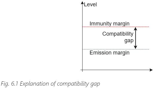
When a piece of equipment or system can function satisfactorily in its electromagnetic environment without introducing intolerable disturbances in that environment, it is called electromagnetic compatibility (EMC). It is important to note that the definition of EMC contains two aspects:
- Immunity: the ability of equipment to function in the presence of some level of electromagnetic interference
- Emission: the unintended emissions from equipment need to be limited to a tolerable level
The difference between the emission margin and the immunity margin is called compatibility gap.
RFI or EMI?
The term radio frequency interference (RFI) is often used interchangeably with EMI. RFI is an older term and refers to the interference of the reception of radio signals (radio, TV, wireless communication). EMI is a newer term which refers broadly to interference of any electrical equipment, including AC drives.
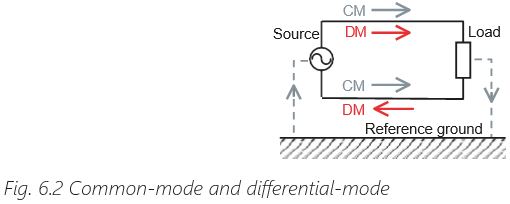
Common-mode and differential mode
When referring to conducted interference the terms common-mode (CM) and differential-mode (DM) are often used.
The differential mode (DM) noise is conducted on both lines of the current loop in opposite directions, in series with the desired signal. The common-mode (CM) noise is conducted on both lines in the same direction and its return path is through a common reference ground.
6.2 EMC and AC Drives
Emission
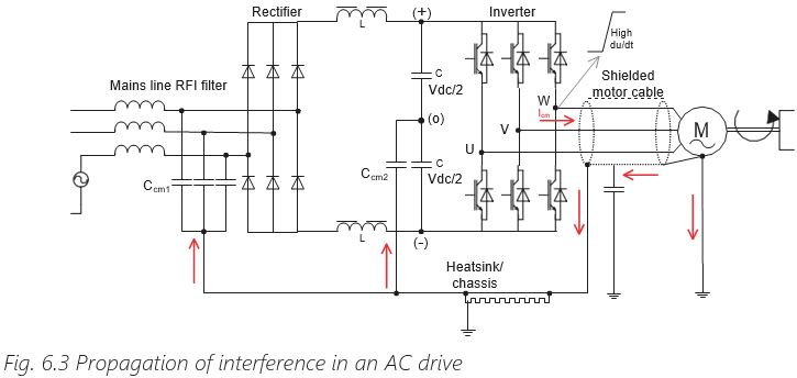
AC drives involve fast switching of voltages (high du/dt rates) in the thousands of V/µs range with amplitudes in the 500 V – 1000 V range (depending on supply voltage) and high current levels. This makes an AC drive a potential source of EMI and their EMC-correct installation needs to be carefully followed.
The noise source is the voltage source inverter that produces a pulse-shaped output voltage with very short rise- and fall times (also expressed as high du/dt). This voltage is applied across parasitic capacitances to ground in the motor cable and motor, which results in a common- mode current:
Icm = Ccm × du
d
where Ccm is the parasitic capacitance to ground.
The common-mode current needs to close the loop and return to its source, the DC-link. Controlling the return path of the common-mode current is a key element of keeping electromagnetic interference under control. Inside the AC drive there are common-mode capacitors – that means capacitors between the AC drive circuit and ground.
The common-mode capacitors can be found in the RFI circuit (Ccm1) or as decoupling capacitors in the DC-link (Ccm2). If a shielded motor cable is used and the motor end of the cable is connected to the motor chassis and the AC drive end is connected to the drive chassis then, ideally, the common-mode current will return to the DC-link via the common-mode capacitors. The common-mode current returning through the mains supply is unwanted because it can cause interference in other equipment connected to the mains. Therefore, this current must be minimized, for example by using RFI filters. When unshielded motor cables are used, then only a part of the common-mode current returns through the AC drive’s chassis and common-mode capacitors thus causing more interference on the mains grid.
Immunity
Immunity, as well as noise emission need be considered in an AC drive application. The control signals connected to an AC drive can be quite susceptible to noise. In general, analogue signals are more susceptible than digital signals. Therefore, it is better to use digital bus communication instead of analogue reference signals. If analogue signals cannot be avoided, a 4 – 20 mA current reference signal is preferred to a 0 – 10 V voltage reference signal because it is less susceptible to noise.
6.3 Grounding and Shielding
Grounding
Grounding means connecting electrical equipment to a common reference ground. The two main reasons for doing this are:
- – Electrical safety: Safety grounding ensures that in the case of the degradation of electrical isolation no live voltage is present on conductive parts that can be touched by a person – thus avoiding the risk of electric shock.
- – Reduced interference: Signal grounding reduces voltage differences that might cause noise emission or susceptibility
It is very important to note that electrical safety always has the highest priority – higher than EMC.
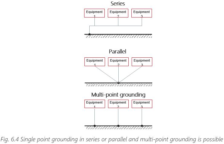
Various types of grounding are common.
The different types of grounding have advantages and disadvantages, but what matters at the end of the day is that the impedance of the grounding connection is as low as possible in order to provide potential equalization of the connected equipment.
Shielding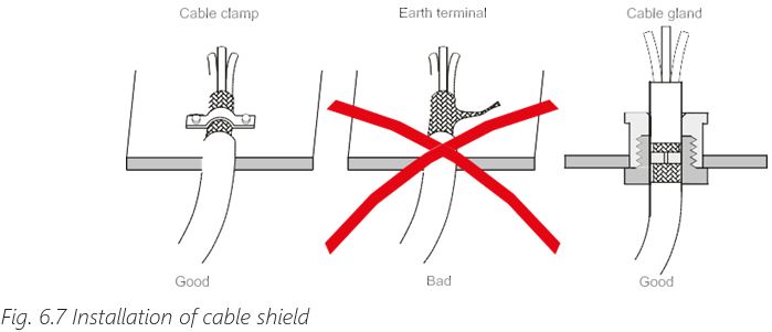
Shielding is used both for immunity (protecting against external interference) and emission (preventing interference to be radiated). In AC drive applications, shielded cables are used both for power (motor cable and brake resistor cable) and for signals (analogue reference signals, bus communication).
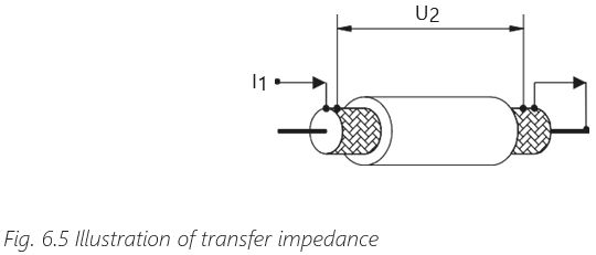
The shielding performance of a cable is indicated by its transfer impedance ZT. The transfer impedance relates a current on the surface of the shield to the voltage drop generated by this current on the opposite surface of the shield:
ZT = U2 , where L is the cable length
l1 x L
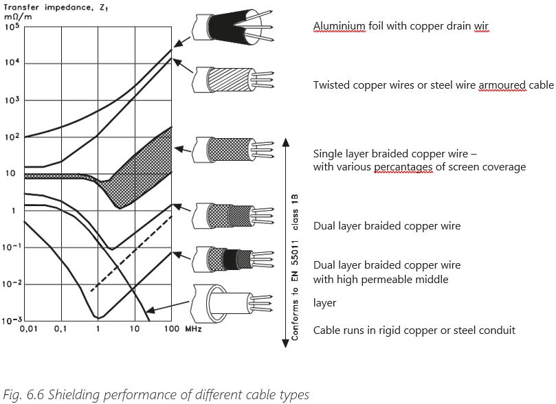
The lower the transfer impedance value the better the shielding performance. The figure below shows typical values of transfer impedance for different kinds of motor cable. The most common type of motor cable is the single layer braided copper wire as it offers a good shielding performance at a reasonable price.
Transfer impedance can be drastically increased by incorrect shield termination. The shield of a cable needs to be connected to the chassis of the equipment through a 360-degree connection. Using “pigtails” to connect the shield increases transfer impedance and ruins the shielding effect of the cable.
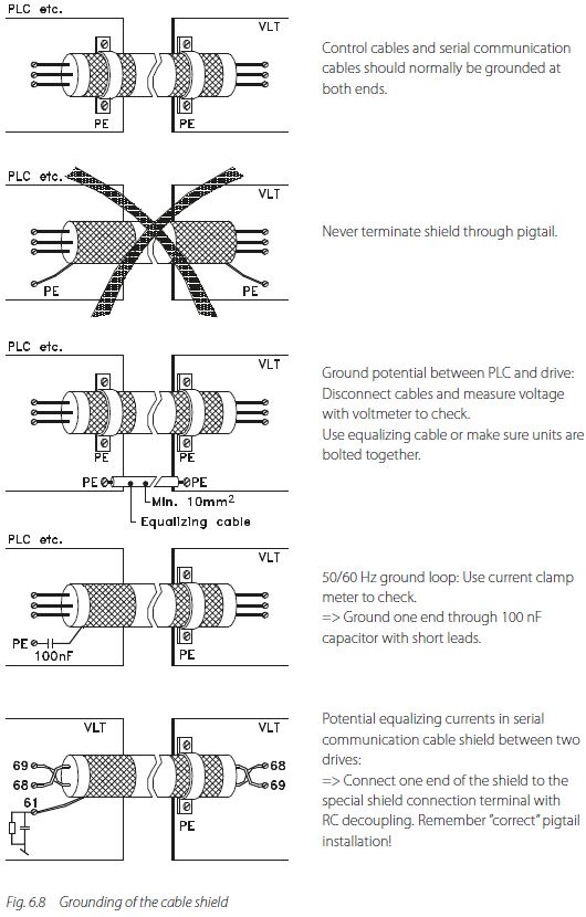
The question about terminating both ends or only one end of a shielded cable often occurs. It is important to realize that the effect of a shielded cable is reduced when only one end is terminated. It is very important to terminate correctly both ends of the motor cable, otherwise interference problems may occur.
The reason why in some situations only one end is terminated has to do with ground loops in signal cables. This means that there is a voltage potential difference between the chassis of the two pieces of equipment that are connected (for example AC drive and PLC) and if the shield connects the two chassis a ground current will occur (with the frequency of 50 Hz/60 Hz). This current then couples into the useful signal disturbing it – in audio applications this is commonly known as “hum”. The best solution is to use an equalizing connection in parallel with the shielded cable. If this is not possible then one end of the shielded cable can be terminated via a 100 nF capacitor. This breaks the ground loop at low frequency (50 Hz) while maintaining the shield connection in the high frequency range. In some equipment this capacitor is already built in.
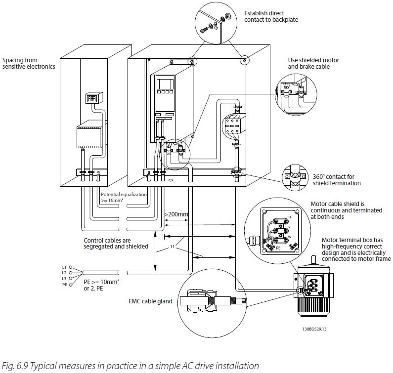
6.4 Installations with AC Drives
It is important to follow good engineering practice when installing AC drives for ensuring electromagnetic compatibility. When designing an installation, an EMC plan can be made following these steps:
- – List components, equipment and areas
- – Divide into potential noise sources and potentially sensitive equipment
- – Classify the cables connecting the equipment (potentially noisy or potentially sensitive)
- – Set requirements and select the equipment
- – Separate potential noise sources from potentially sensitive equipment
- – Control interfaces between noise sources and sensitive equipment
- – Route cables according to the classification
Chapter 5, Sections 5.5 – 5.8.2